3.5 Input Channel Setting
51
3
Chapter 3 Measurement Procedure
The setting workflow for logic channels (standard LOGIC terminals L0A - L0D, expansion LOGIC
terminals L1A - L8D) is explained below.
• If the number of channels in use is low, not all channels may be selectable.
• When input coupling is set to GND, the waveform will have no amplitude and
range setting is not possible.
• Due to the influence of filter attenuation, correct range setting may sometimes
not be possible.
• When making trigger settings, set the vertical axis (voltage axis) range first. If
the range is changed after specifying the trigger, the trigger setting may
change.
• When using the Variable function, set the vertical axis (voltage axis) range first.
If the range is changed after specifying the Variable setting, observation with
sufficient precision may not be possible.
• When using the Variable and Scaling functions together, make the Scaling set-
tings first. If Scaling settings are made after selecting the Variable function, the
intended display result may not be achieved.
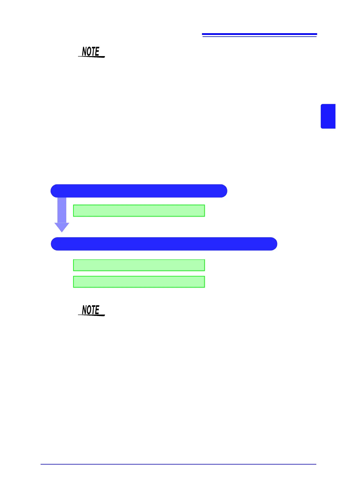
1 Make screen display related settings
Setting logic recording width
See:
"1. Logic Width" (
p.55)
2 Make display color and display position settings
Set waveform display position
Set waveform display color
See:
"2. Waveform Display Position" (
p.55)
"3. Waveform Display Color" (
p.55)
• Waveform display position can be specified in 1% increments.
• Not displayed for X-Y1 and X-Y4 screens.