13.3 Setting FFT Analysis Conditions
222
Octave Filter Setting
Filter features are based on JIS C1513-2002 class 1, class 2 (IEC61260).
After determining the entire power spectrum, the instrument performs octave analysis on the spectral
bands defined by the above filter characteristics.
See:"Octave Filter Characteristics"( p.A26)
Analysis Modes and X/Y Axis Display
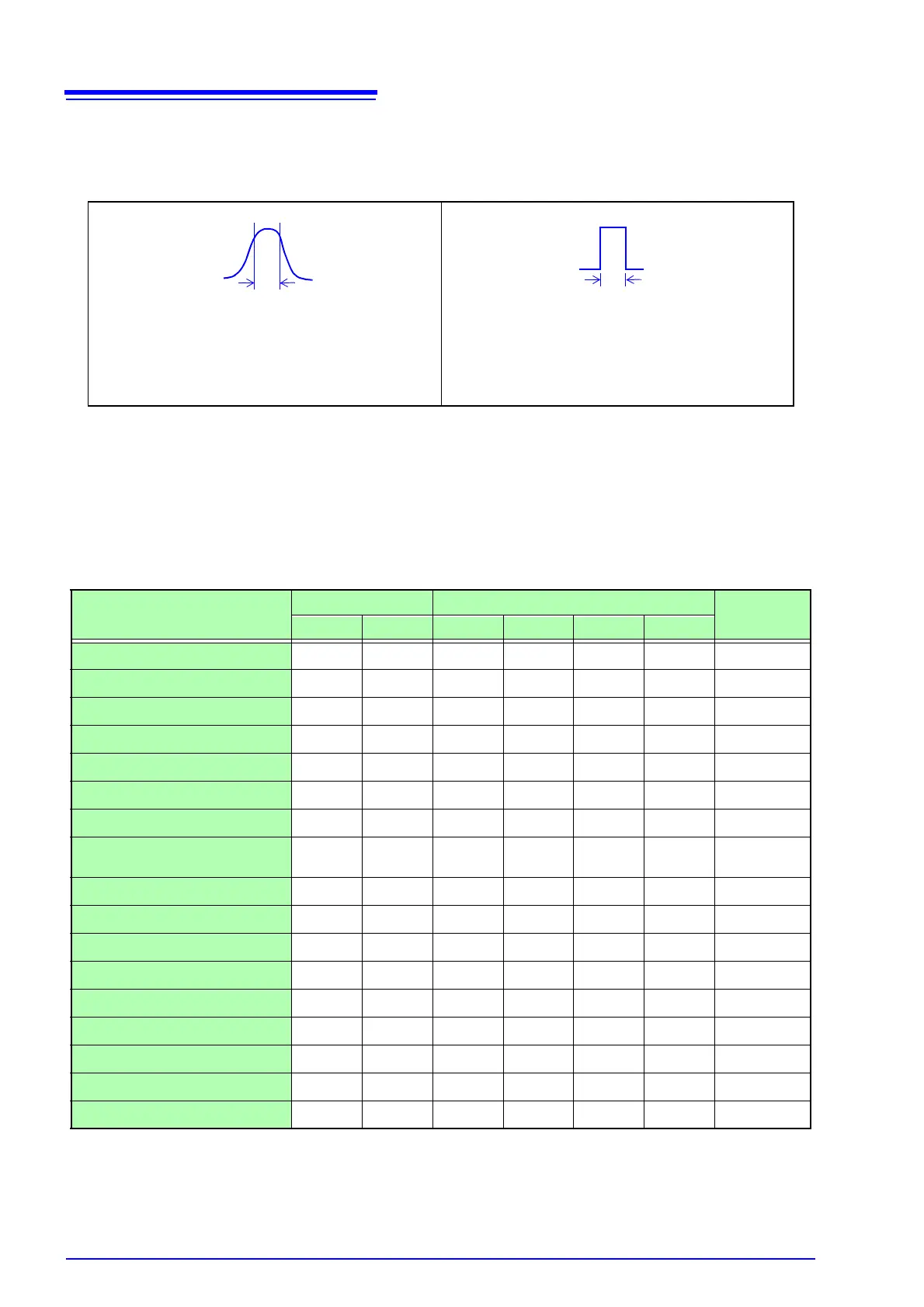
Normal
Filter characteristics approximate those
of an analog filter.
Sharp
Only those spectral component within the
octave band are used for analysis. Spec-
tral components outside of the octave
band are totally ignored.
: Settable, ×: Unsettable
Analysis Mode
X axis Y axis
Nyquist
display
Linear Log Lin-Mag Log-Mag Lin-Real Lin-Imag
OFF
×××××× ×
Storage Waveform
×
××× ×
Histogram
×
××× ×
Linear Spectrum
RMS Spectrum
×
Power Spectrum
×× ×
Power Spectrum Density
×× ×
LPC analysis (Power Spectrum
Density)
×× ×
Transfer Function
Cross Power Spectrum
Impulse Response
×
××× ×
Coherence Function
××× ×
Phase Spectrum
××× ×
Auto-correlation Function
×
××× ×
Cross-correlation Function
×
××× ×
1/1 Octave
×
×× ×
1/3 Octave
×
×× ×
The x/y axes cannot be set when Nyquist Display is selected.