2.1 Install an input module
19
2
Chapter 2 Measurement Preparations
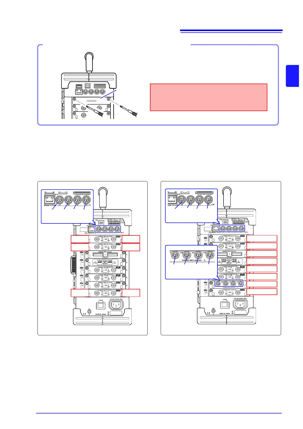
About channel
allocation
When the instrument is positioned vertically as illustrated, module number one is
at the top, and channel number one is at the left of the top.
Information about the input modules installed in the instrument can be verified in the Sys-
tem Configuration list [System Information].
Blank panel
Measurements made without a blank panel
installed may fail to meet specifications because
of temperature instability within the instrument.
If not installing another input module after removal
Right Side
Using the Phillips screwdriver, tighten the two mount-
ing screws.
Ch15
Ch1
Ch16
Ch2
Ch3 Ch4
LA LB LC LD
[1:4] [1:4] [1:4] [1:4]
LA LB LC LD
[1:4] [1:4] [1:4] [1:4]
Module 1
Module 2
Module 3
Module 4
Module 5
Module 6
Module 7
Module 8
L7A L7B L7C L7D
[1:4] [1:4] [1:4] [1:4]
Analog channels only Mix including logic modules