101
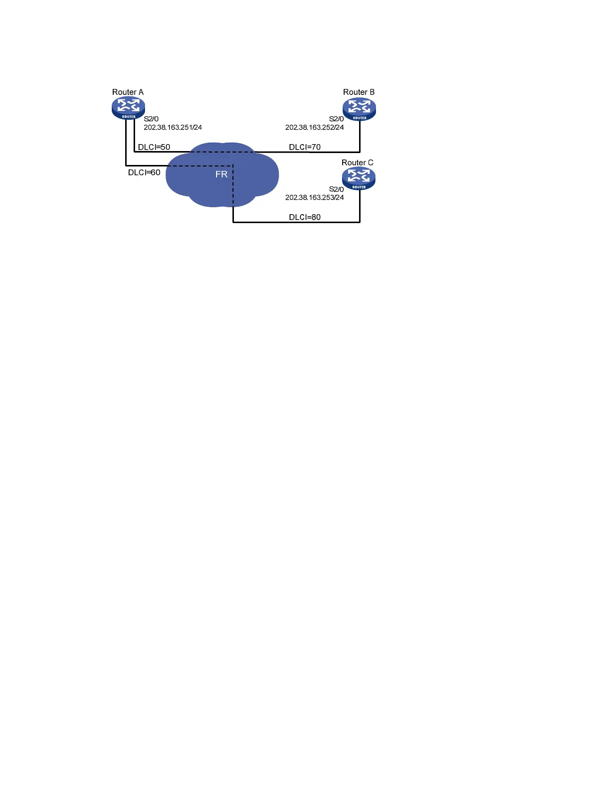
Figure 27 Network diagram
Configuration procedure
1. Configure Router A:
# Assign an IP address to interface Serial 2/0.
<RouterA> system-view
[RouterA] interface serial 2/0
[RouterA-Serial2/0] ip address 202.38.163.251 255.255.255.0
# Enable frame relay on the interface.
[RouterA-Serial2/0] link-protocol fr
[RouterA-Serial2/0] fr interface-type dte
# If the peer router supports InARP, configure dynamic address mappings.
[RouterA-Serial2/0] fr inarp
# Otherwise, configure static address mappings.
[RouterA-Serial2/0] fr map ip 202.38.163.252 50
[RouterA-Serial2/0] fr map ip 202.38.163.253 60
2. Configure Router B:
# Assign an IP address to interface Serial 2/0.
<RouterB> system-view
[RouterB] interface serial 2/0
[RouterB-Serial2/0] ip address 202.38.163.252 255.255.255.0
# Enable frame relay on the interface.
[RouterB-Serial2/0] link-protocol fr
[RouterB-Serial2/0] fr interface-type dte
# If the peer router supports InARP, configure dynamic address mappings.
[RouterB-Serial2/0] fr inarp
# Otherwise, configure a static address mapping.
[RouterB-Serial2/0] fr map ip 202.38.163.251 70
3. Configure Router C:
# Assign an IP address to interface Serial 2/0.
<RouterC> system-view
[RouterC] interface serial 2/0
[RouterC-Serial2/0] ip address 202.38.163.253 255.255.255.0
# Enable frame relay on the interface.
[RouterC-Serial2/0] link-protocol fr
[RouterC-Serial2/0] fr interface-type dte

 Loading...


