248
[RouterB] bridge 5 enable
[RouterB] dlsw local 2.2.2.2
[RouterB] dlsw remote 1.1.1.1
[RouterB] dlsw bridge-set 5
[RouterB] interface ethernet 1/0
[RouterB-Ethernet1/0] bridge-set 5
3. Configure Router C:
# Configure interfaces on Router C to make sure that the local DLSw peer 3.3.3.3 and remote
peer 1.1.1.1 can reach each other. (Details not shown.)
# Configure DLSw on Router C.
<RouterC> system-view
[RouterC] bridge enable
[RouterC] bridge 5 enable
[RouterC] dlsw local 3.3.3.3
[RouterC] dlsw remote 1.1.1.1
[RouterC] dlsw bridge-set 5
[RouterC] interface ethernet 1/0
[RouterC-Ethernet1/0] bridge-set 5
Load balancing configuration example for SDLC-to-LAN
DLSw
Network requirements
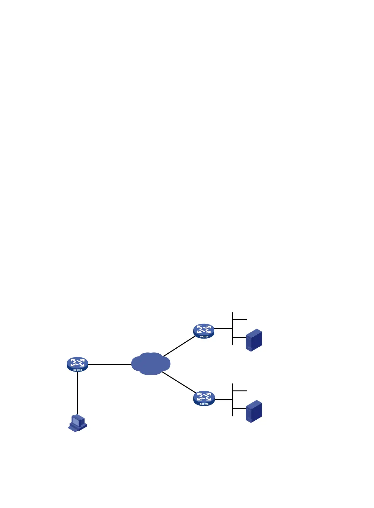
As shown in Figure 86:
• DLSw operates in SDLC-to-LAN mode.
• Configure DLSw on Router A, Router B, and Router C to connect the IBM host with the SNA
host through the Internet.
• Configure DLSw load balancing on Router A.
Figure 86 Network diagram
LAN
LLC2
IBM AS/400
Eth1/0
Internet
Router A
Router B
S2/0
1.1.1.1/24
2.2.2.2/24
SDLC
LAN
LLC2
Host (SNA)
IBM AS/400
Router C
3.3.3.3/24
Eth1/0

 Loading...


