213
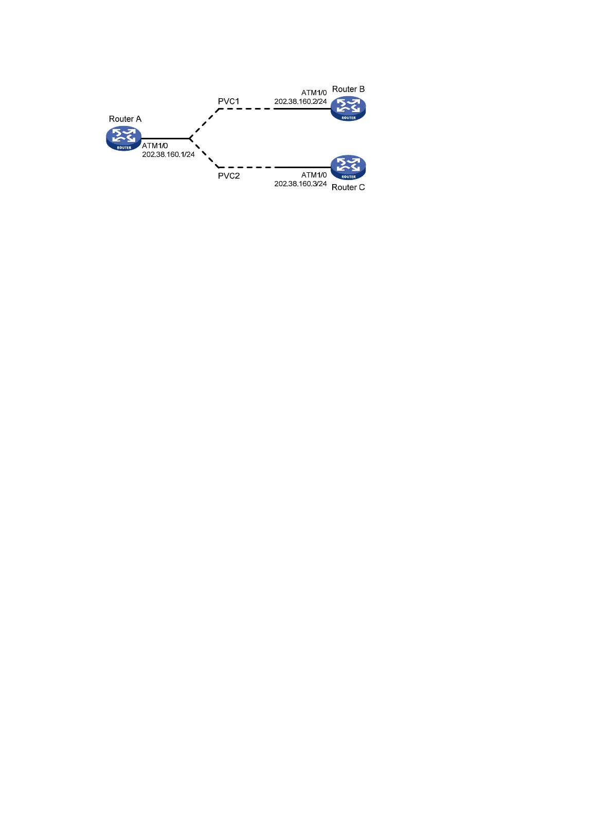
Figure 72 Network diagram
Configuration procedure
Configure Router A
# Configure the ATM interface.
<RouterA> system-view
[RouterA] interface atm 1/0
[RouterA-Atm1/0] ip address 202.38.160.1 255.255.255.0
# Create two PVCs and assign them different transmission priority values.
[RouterA-Atm1/0] pvc 1 0/33
[RouterA-atm-pvc-Atm1/0-0/33-1] map ip 202.38.160.2
[RouterA-atm-pvc-Atm1/0-0/33-1] service ubr 100000
[RouterA-atm-pvc-Atm1/0-0/33-1] transmit-priority 1
[RouterA-atm-pvc-Atm1/0-0/33-1] quit
[RouterA-Atm1/0] pvc 2 0/32
[RouterA-atm-pvc-Atm1/0-0/32-2] map ip 202.38.160.3
[RouterA-atm-pvc-Atm1/0-0/32-2] service ubr 100000
[RouterA-atm-pvc-Atm1/0-0/33-1] transmit-priority 3
After two equal traffic flows exceeding the ATM bandwidth are sent to Router B and Router C, you
can use the display atm pvc-info interface atm 1/0/0 pvc command on Router B and Router C to
view statistics for each PVC (you can make several tests and observe the average statistics). You
can see that the PVC with higher priority receives more packets than that with lower priority. The
PVC with the higher priority takes preference in getting bandwidth and other PVCs (if there are many
and with different priority values), regardless of their priority values, are treated equally in terms of
bandwidth allocation.
Troubleshooting ATM
Link state error in IPoA application
Symptom
When IPoA is used, the link state is down.
Solution
Make sure the optical fiber is plugged in correctly.
Make sure the local IP address has been configured.
Make sure the PVC is successfully created and communication between cards is normal.

 Loading...


