359
# Configure Serial 2/0 and an XOT route.
[RouterC] interface serial 2/0
[RouterC-Serial2/0] link-protocol x25 dce ietf
[RouterC-Serial2/0] x25 vc-range in-channel 10 20 bi-channel 30 1024
[RouterC-Serial2/0] x25 xot pvc 2 10.1.1.1 interface serial 2/0 pvc 1
# Configure Ethernet 1/1.
[RouterC] interface ethernet 1/1
[RouterC-Ethernet1/1] ip address 10.1.1.2 255.0.0.0
SVC application of X.25 over FR
Network requirements
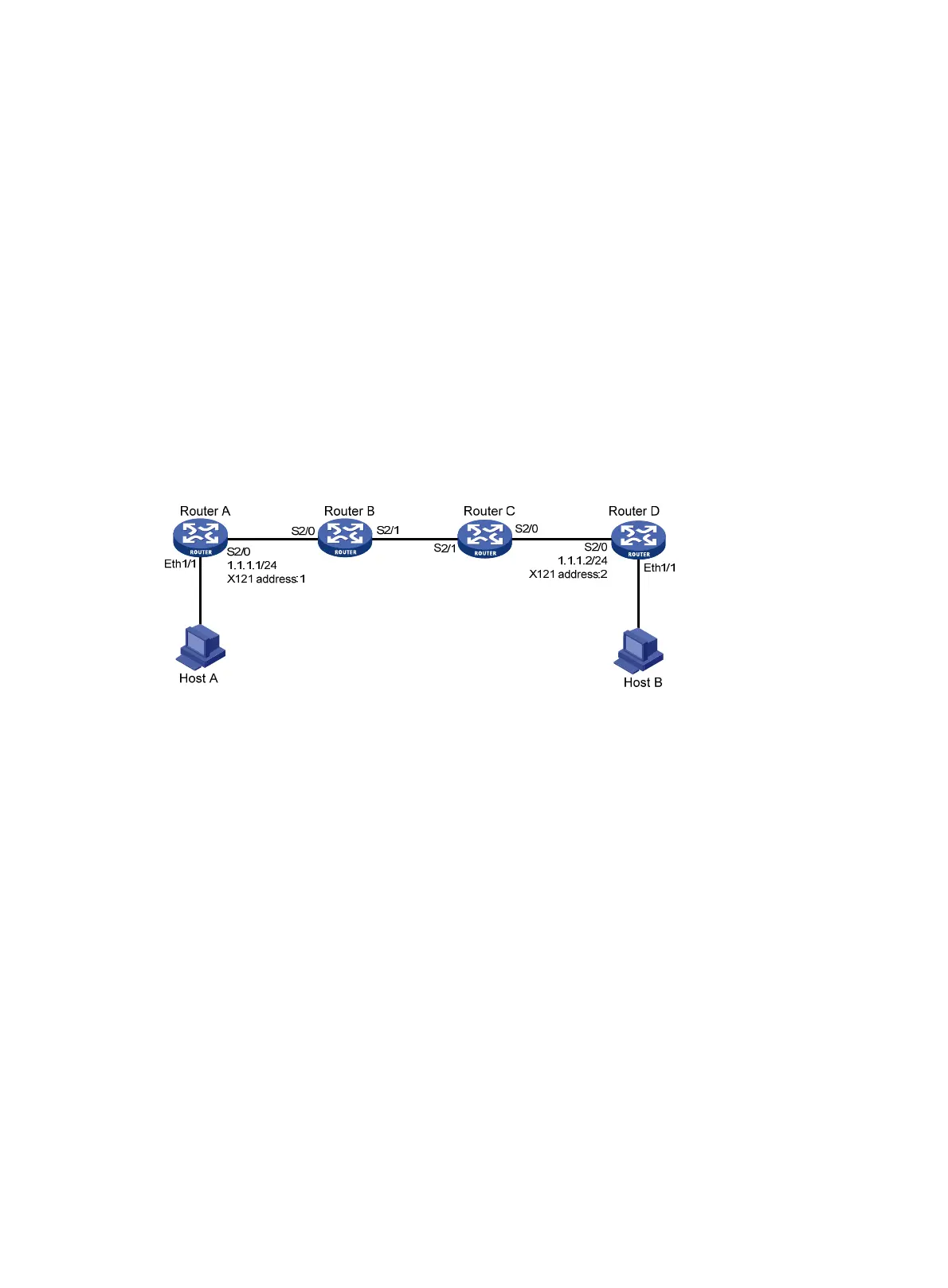
In Figure 144, Router A is connected to Router B, Router C to Router D through X.25, and Router B is
connected to Router C through FR.
Configure FR Annex G DLCI 100 on the two routers to interconnect the two X.25 networks, enabling
Host A and Host B to communicate with each other.
Figure 144 Network diagram
Configuration procedure
1. Configure Router A:
# Configure X.25 basic functions.
<RouterA> system-view
[RouterA] interface serial 2/0
[RouterA-Serial2/0] link-protocol x25 dte
[RouterA-Serial2/0] x25 x121-address 1
[RouterA-Serial2/0] x25 map ip 1.1.1.2 x121-address 2
[RouterA-Serial2/0] ip address 1.1.1.1 255.0.0.0
2. Configure Router D:
# Configure X.25 basic functions.
<RouterD> system-view
[RouterD] interface serial 2/0
[RouterD-Serial2/0] link-protocol x25 dte
[RouterD-Serial2/0] x25 x121-address 2
[RouterD-Serial2/0] x25 map ip 1.1.1.1 x121-address 1
[RouterD-Serial2/0] ip address 1.1.1.2 255.0.0.0
3. Configure Router B:
# Enable X.25 switching.
<RouterB> system-view
 Loading...


