238
<RouterB> system-view
[RouterB] dlsw local 2.2.2.2
[RouterB] dlsw remote 1.1.1.1
[RouterB] interface serial 2/0
[RouterB-Serial2/0] link-protocol sdlc
[RouterB-Serial2/0] sdlc enable dlsw
[RouterB-Serial2/0] sdlc status primary
[RouterB-Serial2/0] sdlc controller c1
[RouterB-Serial2/0] sdlc mac-map remote 0000-1111-00c1 c1
[RouterB-Serial2/0] sdlc mac-map local 0000-2222-0000
[RouterB-Serial2/0] baudrate 9600
[RouterB-Serial2/0] code nrzi
After this step, the SDLC LANs across the WAN are interconnected.
Configuring DLSw for SDLC-to-LAN remote media
translation
Network requirements
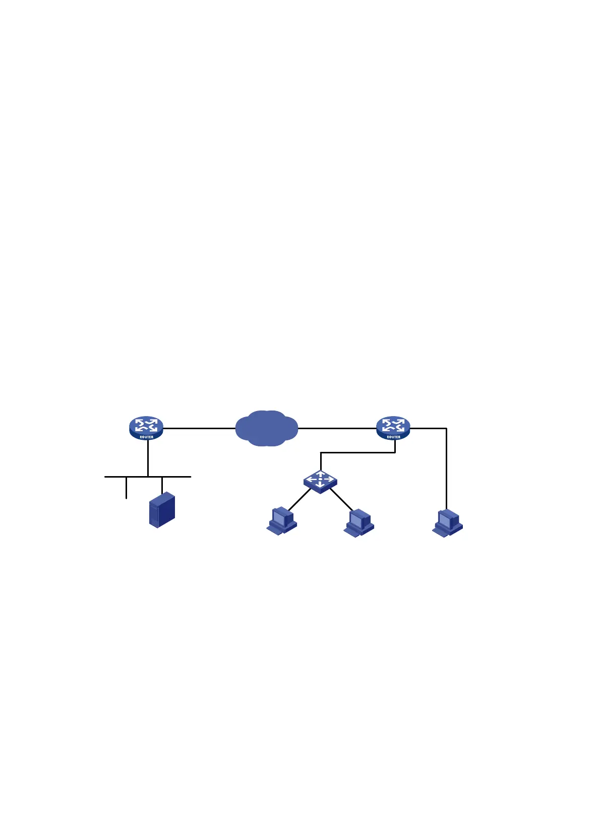
As shown in Figure 79, Host A and Host B are PU2.0 nodes (ATM), and Host C is a PU2.1 node
(OS2). Configure DLSw on Router A and Router B, using NRZ encoding on the port connected with
the multiplexer and NRZI encoding on the port connected with Host C, so the IBM host can
communicate with all the SNA PCs over the Internet.
Figure 79 Network diagram
Configuration procedure
1. Configure Router A:
# Configure interfaces on Router A to make sure that the local DLSw peer 1.1.1.1 and remote
peer 2.2.2.2 can reach each other. (Details not shown.)
# Configure DLSw on Router A.
<RouterA> system-view
[RouterA] bridge enable
[RouterA] bridge 1 enable
[RouterA] dlsw local 1.1.1.1
[RouterA] dlsw remote 2.2.2.2
[RouterA] dlsw bridge-set 1
[RouterA] interface ethernet 1/0
Host C(SNA )
SDLC address: 0xC3
Internet
1.1.1.1/24
IBM AS/400
Router A Router B
S2/0
2.2.2.2/24 S2/1
Eth1/0
LAN
LLC2
Host B(SNA )
SDLC address: 0xC2
Host A(SNA )
SDLC address: 0xC1
MAC address: 0028-3300-2af5
SDLC
SDLC

 Loading...


