2
SLIP encapsulation on
synchronous/asynchronous interfaces
configuration example
Network requirements
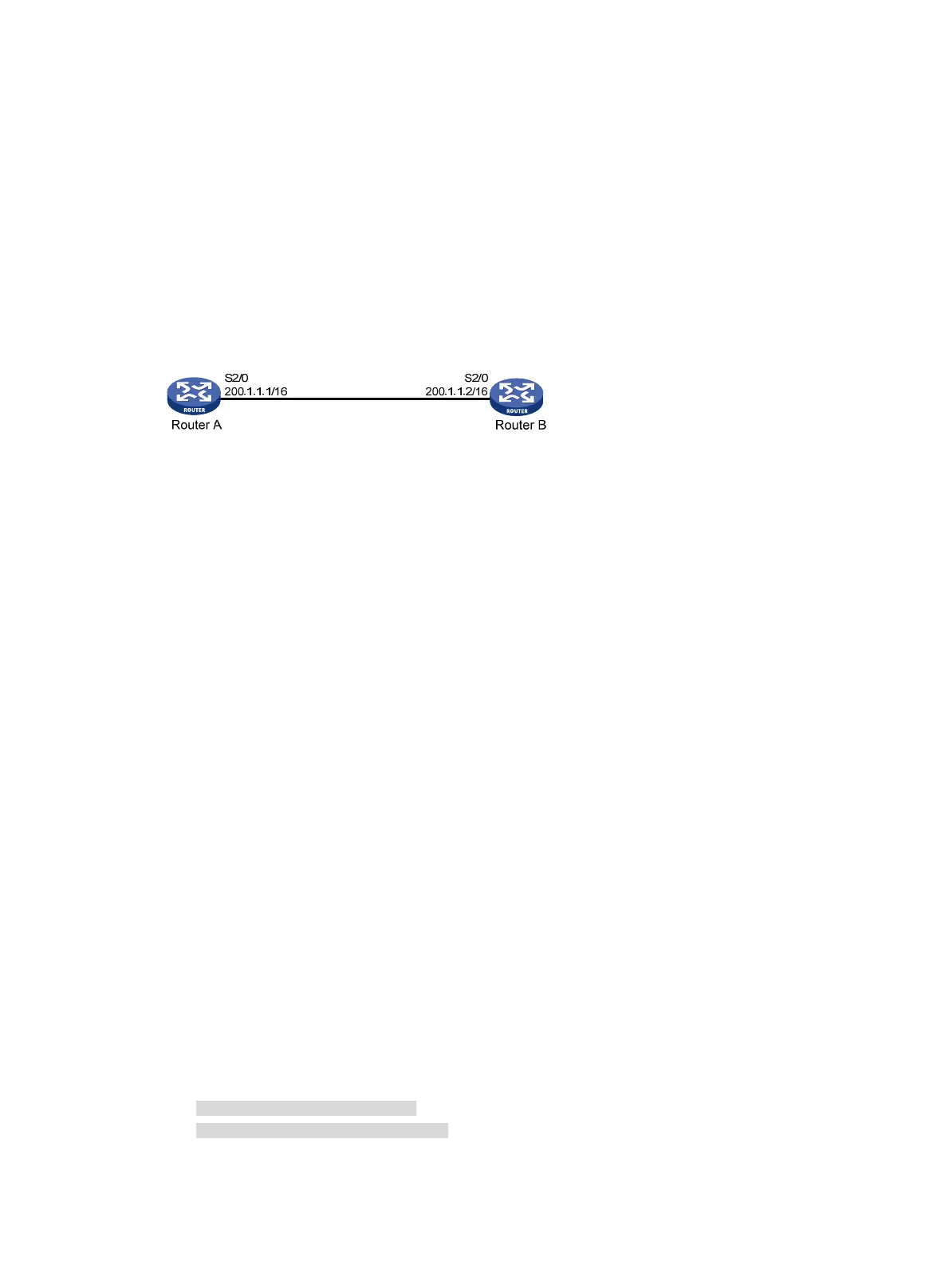
As shown in Figure 1, Router A and Router B are connected by synchronous/asynchronous interface
Serial 2/0. The link layer protocol is SLIP.
Figure 1 Network diagram
Configuration procedure
1. Configure Router A:
# Configure interface Serial 2/0 to operate in asynchronous and protocol mode.
<RouterA> system-view
[RouterA] interface serial 2/0
[RouterA-Serial2/0] physical-mode async
[RouterA-Serial2/0] async mode protocol
# Enable SLIP encapsulation on interface Serial 2/0.
[RouterA-Serial2/0] link-protocol slip
# Assign an IP address to interface Serial 2/0.
[RouterA-Serial2/0] ip address 200.1.1.1 16
2. Configure Router B:
# Configure interface Serial 2/0 to operate in asynchronous and protocol mode.
<RouterB> system-view
[RouterB] interface serial 2/0
[RouterB-Serial2/0] physical-mode async
[RouterB-Serial2/0] async mode protocol
# Enable SLIP encapsulation on interface Serial 2/0.
[RouterB-Serial2/0] link-protocol slip
# Assign an IP address to interface Serial 2/0.
[RouterB-Serial2/0] ip address 200.1.1.2 16
3. Verify the configuration:
Use the display interface command to view the information about interface Serial 2/0. The
physical layer status and link layer status of Serial 2/0 are both up, and Router A and Router B
can successfully ping each other.
[RouterB-Serial2/0] display interface serial 2/0
Serial2/0 current state: UP
Line protocol current state: UP
Description: Serial2/0 Interface
The Maximum Transmit Unit is 1500, Hold timer is 10(sec)

 Loading...


