353
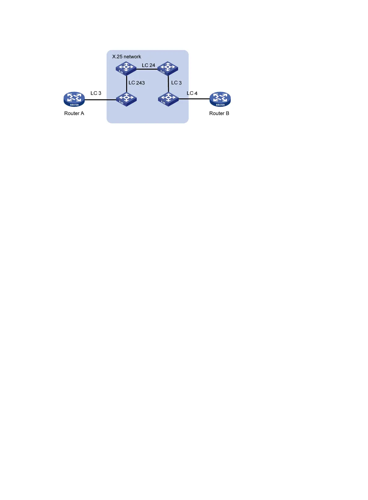
Figure 140 One virtual circuit consisting of several logical channels
The PVC 3 and PVC 4 mentioned in the example refer to the numbers of the logical channels
between the routers and the PBXs directly connected. The two sides of the PVC can identify the
same PVC by using their logical channel numbers, however, without the likelihood of causing
any mistake. This is why no strict distinction is made between "virtual circuit" and "logical
channel."
Verifying the configuration
Ping Router B from Router A to verify Router A can reach Router B.
# Display the X.25 address mapping table on Router A.
[RouterA] display x25 map
Interface: Serial2/0(protocol status is UP)
ip 192.149.13.2 X.121 address:1004358902
Map-type: PVC_MAP VC-number: 1
Facility:
BROADCAST;
PACKET_SIZE: I 512 O 512 ;
WINDOW_SIZE: I 5 O 5 ;
X.25 subinterface configuration example
Network requirements
Configure multiple subinterfaces on a physical interface for connecting to multiple network
segments.
In Figure 141,
Router A is configured with two subinterfaces, which are connected with Router B and
Router C. Router D operates as an X.25 switch.
Configure the subinterfaces, so that Router A can communicate with Router B and Router C,
respectively.

 Loading...


