103
[RouterB-Serial2/0] fr inarp
# Otherwise, configure a static address mapping.
[RouterB-Serial2/0] fr map ip 202.38.163.251 70
3. Configure Router C:
# Assign an IP address to interface Serial 2/0.
<RouterC> system-view
[RouterC] interface serial 2/0
[RouterC-Serial2/0] ip address 202.38.163.253 255.255.255.0
# Enable frame relay on the interface.
[RouterC-Serial2/0] link-protocol fr
[RouterC-Serial2/0] fr interface-type dte
# If the peer router supports IND, configure dynamic address mappings.
[RouterC-Serial2/0] fr ind
# Otherwise, configure a static address mapping.
[RouterC-Serial2/0] fr map ip 202.38.163.251 80
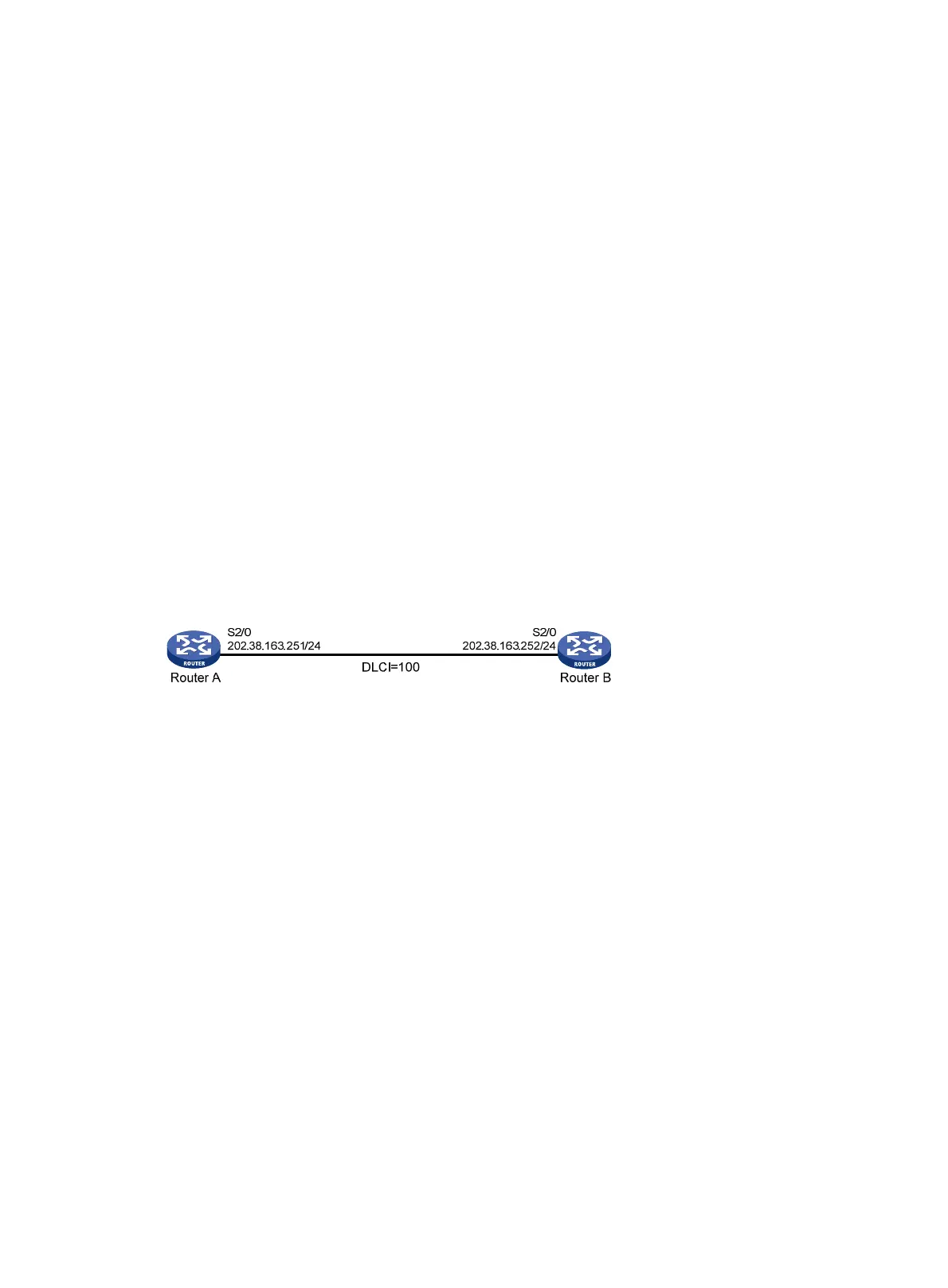
Connecting LANs with a dedicated line
Network requirements
As shown in Figure 29, two routers are directly connected with serial interfaces. Router A operates in
DCE mode, and Router B operates in DTE mode.
Figure 29 Network diagram
Configuration procedure
Method 1: On main interfaces
1. Configure Router A:
# Assign an IP address to interface Serial 2/0.
<RouterA> system-view
[RouterA] interface serial 2/0
[RouterA-Serial2/0] ip address 202.38.163.251 255.255.255.0
# Enable frame relay on the interface and configure the interface to operate in DCE mode.
[RouterA-Serial2/0] link-protocol fr
[RouterA-Serial2/0] fr interface-type dce
# Configure a local virtual circuit.
[RouterA-Serial2/0] fr dlci 100
2. Configure Router B:
# Assign an IP address to interface Serial 2/0.
<RouterB> system-view
[RouterB] interface serial 2/0
[RouterB-Serial2/0] ip address 202.38.163.252 255.255.255.0
# Enable frame relay on the interface and configure the interface to operate in DTE mode.
[RouterB-Serial2/0] link-protocol fr
 Loading...


