308
# Configure the IP address of the synchronous serial interface formed by timeslot bundling on
interface T1 2/0.
<RouterC> system-view
[RouterC] controller t1 2/0
[RouterC-T1 2/0] channel-set 0 timeslot-list 1-24
[RouterC-T1 2/0] quit
[RouterC] interface serial 2/0:0
[RouterC-Serial2/0:0] ip address 1.1.1.2 24
3. Configure the EtoPPP device (Router B):
# Create the EtoPPP mapping for forwarding the traffic between the CE and the PE.
<RouterB> system-view
[RouterB] controller t1 2/0
[RouterB-T1 2/0] channel-set 0 timeslot-list 1-24
[RouterB-T1 2/0] quit
[RouterB] etoppp translate interface ethernet 1/1 serial 2/0:0 ip-address 1.1.1.1
1.1.1.2
EtoFR configuration example
Network requirements
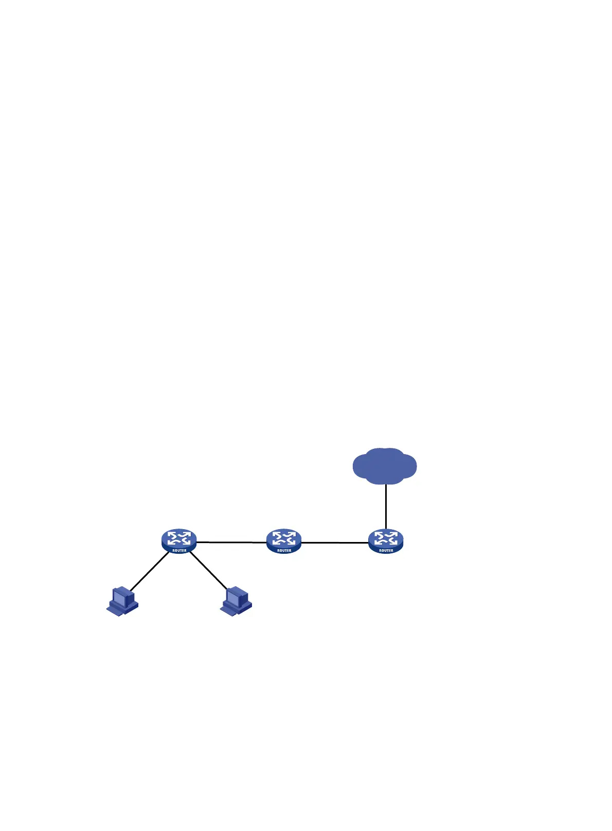
As shown in Figure 119 , Router A (the CE) is the gateway for a LAN and is connected to Router B (the
EtoFR device) through an Ethernet interface. Router B is connected to Router C (the PE) through an
FR-encapsulated serial interface formed by bundling timeslots on a T1 line.
Map the Ethernet interface to the FR interface on Router B through EtoFR to forward traffic between
the two interfaces at Layer 2.
Figure 119 Network diagram
Configuration procedure
1. Configure the CE (Router A):
# Configure the IP address of interface Ethernet 1/1 on Router A.
<RouterA> system-view
[RouterA] interface ethernet 1/1
[RouterA-Ethernet1/1] ip address 1.1.1.1 24
2. Configure the PE (Router C):
Serial 2/0:0
1.1.1.2/24
DLCI = 20
Serial 2/0:0
DLCI = 20
EtoFR device
Internet
Router CRouter B
Router A
Eth 1/1
Eth 1/1
1.1.1.1/24
PECE
Host B
Host A
 Loading...


