116
# Bundle Serial 2/0 and Serial 2/1 to MFR4.
[RouterB] interface serial 2/0
[RouterB-Serial2/0] link-protocol fr mfr 4
[RouterB-Serial2/0] quit
[RouterB] interface serial 2/1
[RouterB-Serial2/1] link-protocol fr mfr 4
MFR switched connection configuration example
Network requirements
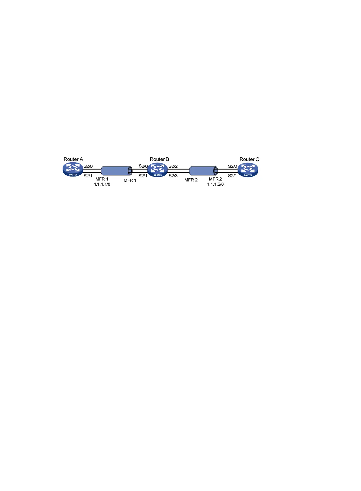
As shown in Figure 35, Router A and Router C are connected through MFR to Router B where MFR
switching is enabled.
Figure 35 Network diagram
Configuration procedure
1. Configure Router A:
# Configure interface MFR1.
<RouterA> system-view
[RouterA] interface mfr 1
[RouterA-MFR1] ip address 1.1.1.1 255.0.0.0
[RouterA-MFR1] quit
# Add Serial 2/0 and Serial 2/1 to interface MFR1.
[RouterA] interface serial 2/0
[RouterA-Serial2/0] link-protocol fr mfr 1
[RouterA-Serial2/0] quit
[RouterA] interface serial 2/1
[RouterA-Serial2/1] link-protocol fr mfr 1
[RouterA-Serial2/1] quit
2. Configure Router B:
# Enable frame relay switching.
<RouterB> system-view
[RouterB] fr switching
# Configure interface MFR1.
[RouterB] interface mfr 1
[RouterB-MFR1] fr interface-type dce
[RouterB-MFR1] fr dlci 100
[RouterB-fr-dlci-MFR1-100] quit
[RouterB-MFR1] quit
# Configure interface MFR2.
[RouterB] interface mfr 2
[RouterB-MFR2] fr interface-type dce
[RouterB-MFR2] fr dlci 200
[RouterB-fr-dlci-MFR2-200] quit

 Loading...


