303
[RouterB-Dialer2] link-protocol ppp
[RouterB-Dialer2] bridge-set 1
[RouterB-Dialer2] dialer enable-circular
[RouterB-Dialer2] dialer-group 1
[RouterB-Dialer2] dialer number 660206
[RouterB-Dialer2] quit
# Add Ethernet 1/1 to bridge set 1.
[RouterB] interface ethernet1/1
[RouterB-Ethernet1/1] bridge-set 1
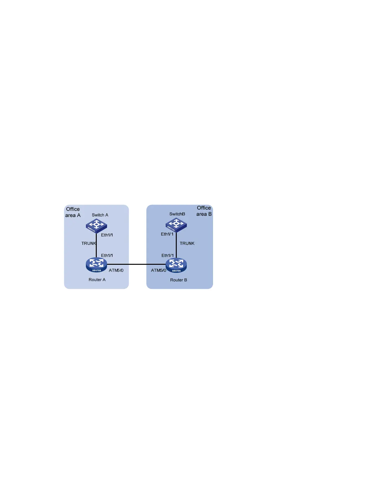
VLAN transparency configuration example
Network requirements
As shown in Figure 117 , the trunk interfaces of Switch A and Switch B are assigned to the same
VLAN.
Enable VLAN transparency on interfaces Ethernet 1/1 and ATM 5/0 on both Router A and Router B
so the two office areas can communicate within the same VLAN.
Figure 117 Network diagram
Configuration procedure
1. Configure Router A:
# Enable the bridging function.
<RouterA> system-view
[RouterA] bridge enable
[RouterA] bridge 2 enable
# Add Ethernet 1/1 to bridge set 2 and enable VLAN transparency on Ethernet 1/1. Add ATM
5/0 to bridge-set 2 and enable VLAN transparency.
[RouterA] interface ethernet 1/1
[RouterA-Ethernet1/1] bridge-set 2
[RouterA-Ethernet1/1] bridge vlanid-transparent-transmit enable
[RouterA-Ethernet1/1] quit
[RouterA] interface atm5/0
[RouterA-Atm5/0] bridge-set 2
[RouterA-Atm5/0] bridge vlanid-transparent-transmit enable
[RouterA-Atm5/0] pvc to_r2 1/100
[RouterA-Atm5/0-1/100-to_r2] map bridge-group broadcast
2. Configure Router B:

 Loading...


