156
# Set interface Serial 2/0 to operate in asynchronous protocol mode, configure information for
PPP authentication, and assign the interface to dialer bundle 1.
[RouterC] interface serial 2/0
[RouterC-Serial2/0] physical-mode async
[RouterC-Serial2/0] async mode protocol
[RouterC-Serial2/0] dialer bundle-member 1
[RouterC-Serial2/0] link-protocol ppp
[RouterC-Serial2/0] ppp authentication-mode pap
[RouterC-Serial2/0] ppp pap local-user userc password simple userc
[RouterC-Serial2/0] quit
# Configure the user interface to be used and enable modem dial-in and dial-out on it.
[RouterC] user-interface tty1
[RouterC-ui-tty1] modem both
Configuration example for DCC on ISDN
Network requirements
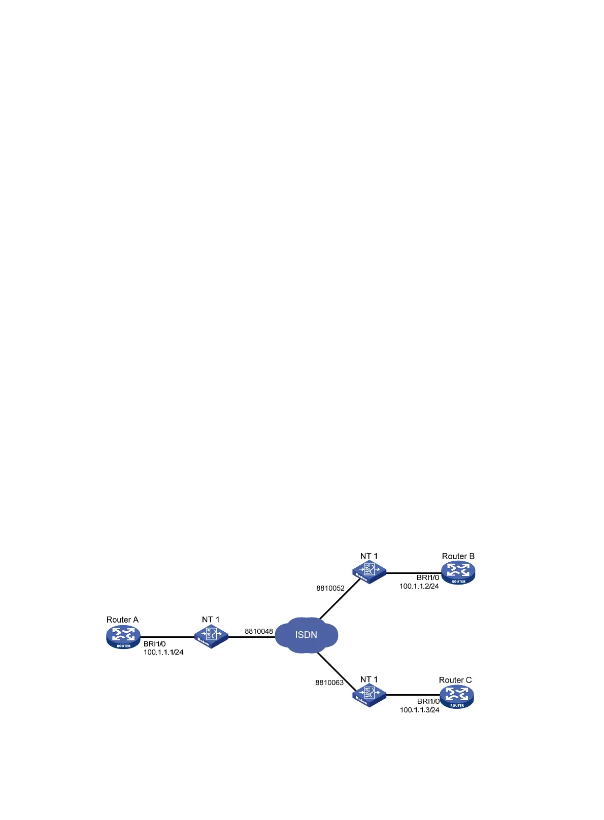
Figure 49 presents a scenario for C-DCC implementation, where:
• On Router A, interface BRI 1/0 is assigned an IP address 100.1.1.1/24.
• On Router B, interface BRI 1/0 is assigned an IP address 100.1.1.2/24.
• On Router C, interface BRI 1/0 is assigned an IP address 100.1.1.3/24.
• The BRI 1/0 interfaces on these three routers are located on the same network segment.
Figure 50 p
resents a scenario for RS-DCC implementation, where:
• On Router A, interface Dialer 0 is assigned an IP address 100.1.1.1/24 and Dialer 1 an IP
address 122.1.1.1/24.
• On Router B, interface Dialer 0 is assigned an IP address 100.1.1.2/24.
• On Router C, interface Dialer 0 is assigned an IP address 122.1.1.2/24.
• The Dialer 0 interfaces on Router A and Router B are located on the same network segment, so
are the Dialer 1 interface on Router A and the Dialer 0 interface on Router C.
Allow Router A to call Router B and Router C from multiple interfaces, but disable Router B and
Router C from calling each other in both C-DCC and RS-DCC approaches.
Figure 49 Network diagram for C-DCC application on ISDN

 Loading...


