110
# Configure interface Serial 2/0 to operate in DTE mode.
[RouterB-Serial2/0] fr interface-type dte
# Create an IP address map entry and enable FRF.9 compression on interface Serial 2/0.
[RouterB-Serial2/0] fr map ip 10.110.40.1 100 compression frf9
Verifying the configuration
# Ping Router B from Router A.
<RouterA> ping 10.110.40.2
PING 10.110.40.2: 56 data bytes, press CTRL_C to break
Reply from 10.110.40.2: bytes=56 Sequence=1 ttl=255 time=13 ms
Reply from 10.110.40.2: bytes=56 Sequence=2 ttl=255 time=12 ms
Reply from 10.110.40.2: bytes=56 Sequence=3 ttl=255 time=12 ms
Reply from 10.110.40.2: bytes=56 Sequence=4 ttl=255 time=12 ms
Reply from 10.110.40.2: bytes=56 Sequence=5 ttl=255 time=12 ms
--- 10.110.40.2 ping statistics ---
5 packet(s) transmitted
5 packet(s) received
0.00% packet loss
round-trip min/avg/max = 12/12/13 ms
# Display statistics about packet compression on Router A.
<RouterA> display fr compress
Serial2/0
-DLCI:100
enable frame-relay compression
uncompressed bytes send/receive : 595/595
compressed bytes send/receive : 159/157
1 min avg ratio send/receive : 0.000/0.000
5 min avg ratio send/receive : 0.267/0.264
Frame relay FRF.20 IP header compression configuration
example
Network requirements
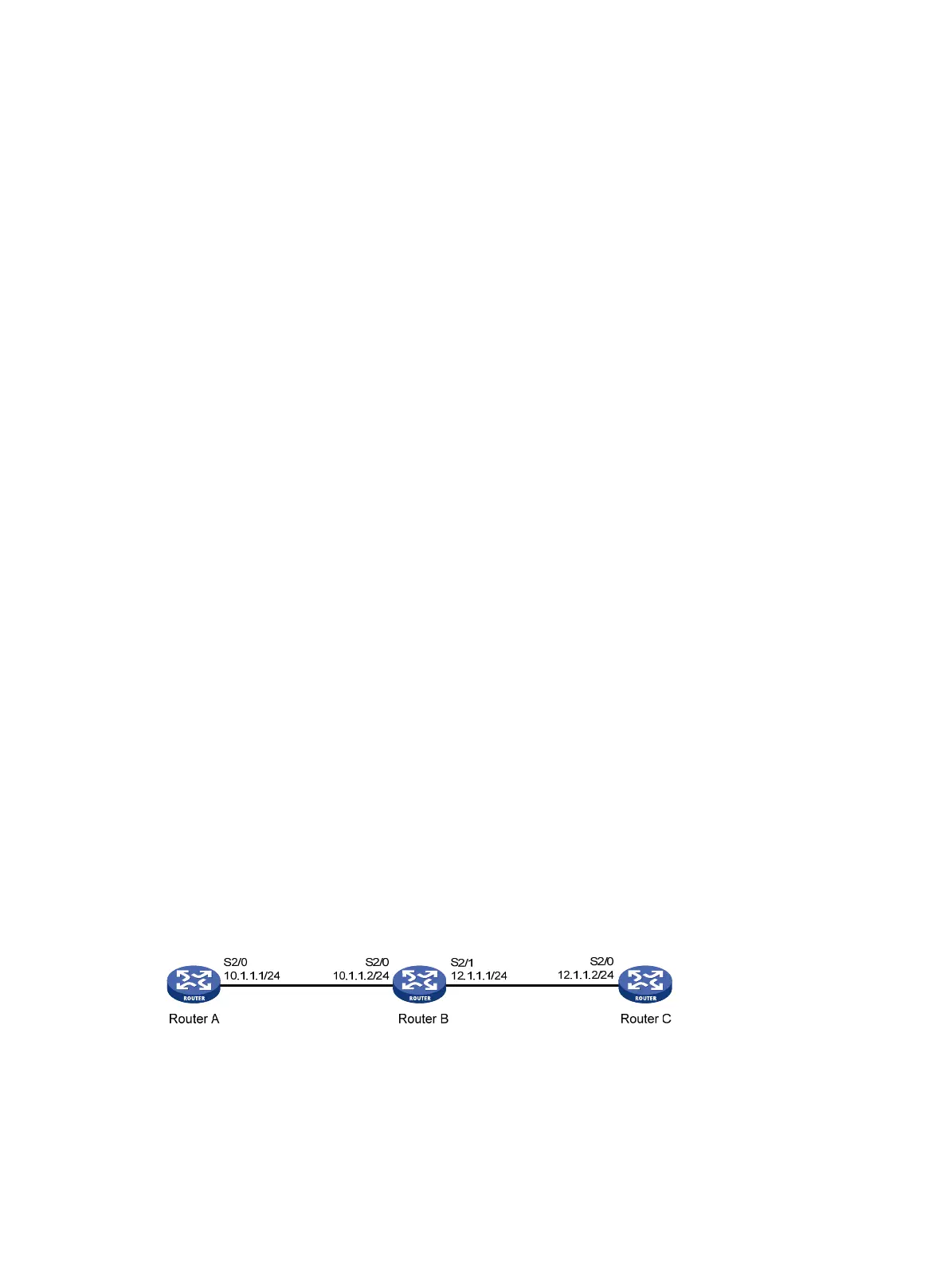
As shown in Figure 32, Router A and Router B are interconnected with a frame relay link. Enable
FRF.20 IP compression on the two routers.
Figure 32 Network diagram
Configuration procedure
1. Configure Router A:
# Enable frame relay on interface Serial 2/0.
<RouterA> system-view
[RouterA] interface serial 2/0

 Loading...


