349
Connecting the router to X.25 public packet network
Network requirements
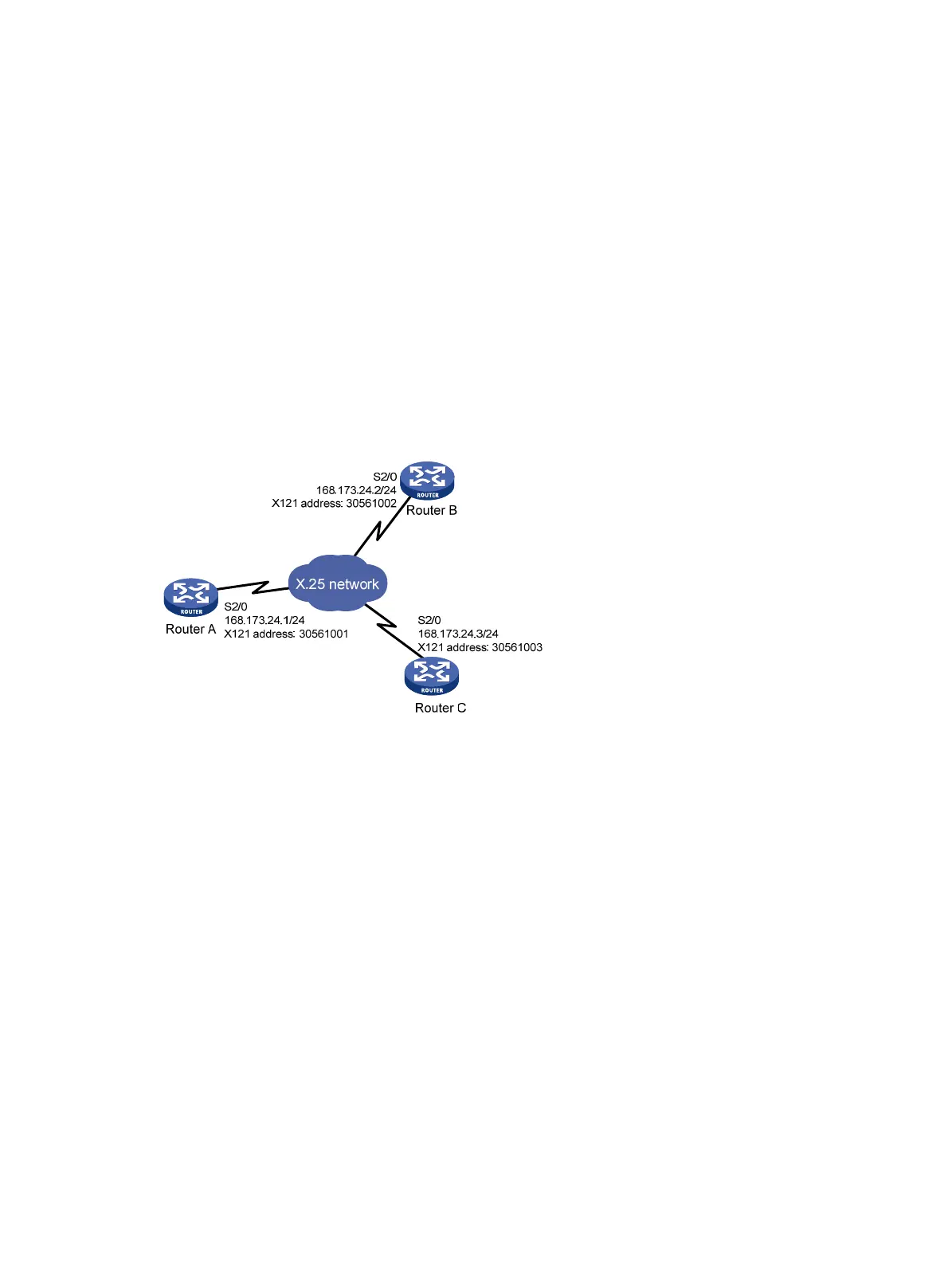
As shown in Figure 138, Router A, Router B, and Router C are connected to the same X.25 network.
The requirements are:
• The IP addresses of the interfaces Serial 2/0 of the three routers are 168.173.24.1/24,
168.173.24.2/24, and 168.173.24.3/24.
• The X.121 addresses assigned to the three routers are 30561001, 30561002, and 30561003.
• The standard window size supported by the packet network: both receiving window and
sending window are 5.
• The standard maximum packet size: both the maximum receiving packet size and the
maximum sending packet size are 512.
• Channel range: permanent virtual circuit range, incoming-only channel range and
outgoing-only channel range are disabled, and two-way channel range is [1, 32].
Figure 138 Network diagram
Configuration procedure
1. Configure Router A:
# Assign an IP address for the interface.
<RouterA> system-view
[RouterA] interface serial 2/0
[RouterA-Serial2/0] ip address 168.173.24.1 255.255.255.0
# Access the public packet network, and configure the router to operate in DTE mode.
[RouterA-Serial2/0] link-protocol x25 dte
[RouterA-Serial2/0] x25 x121-address 30561001
[RouterA-Serial2/0] x25 window-size 5 5
[RouterA-Serial2/0] x25 packet-size 512 512
[RouterA-Serial2/0] x25 vc-range bi-channel 1 32
[RouterA-Serial2/0] x25 map ip 168.173.24.2 x121-address 30561002
[RouterA-Serial2/0] x25 map ip 168.173.24.3 x121-address 30561003
[RouterA-Serial2/0] shutdown
[RouterA-Serial2/0] undo shutdown
2. Configure Router B:
# Assign an IP address for the interface.
<RouterB> system-view

 Loading...


