219
Configuration procedure
1. Configure Router A:
<RouterA> system-view
[RouterA] interface pos 5/0
[RouterA-Pos5/0] clock master
[RouterA-Pos5/0] link-protocol hdlc
[RouterA-Pos5/0] ip address 12.1.1.1 24
[RouterA-Pos5/0] quit
2. Configure Router B:
<RouterB> system-view
[RouterB] interface pos 5/0
[RouterB-Pos5/0] link-protocol hdlc
[RouterB-Pos5/0] ip address 12.1.1.2 24
After the configuration, Router A and Router B should be able to ping each other. Take the
output on Router A as an example.
[RouterA] ping 12.1.1.2
PING 12.1.1.2: 56 data bytes, press CTRL_C to break
Reply from 12.1.1.2: bytes=56 Sequence=1 ttl=255 time=126 ms
Reply from 12.1.1.2: bytes=56 Sequence=2 ttl=255 time=1 ms
Reply from 12.1.1.2: bytes=56 Sequence=3 ttl=255 time=1 ms
Reply from 12.1.1.2: bytes=56 Sequence=4 ttl=255 time=1 ms
Reply from 12.1.1.2: bytes=56 Sequence=5 ttl=255 time=10 ms
--- 12.1.1.2 ping statistics ---
5 packet(s) transmitted
5 packet(s) received
0.00% packet loss
round-trip min/avg/max = 1/27/126 ms
HDLC in conjunction with IP unnumbered interface
configuration example
Network requirements
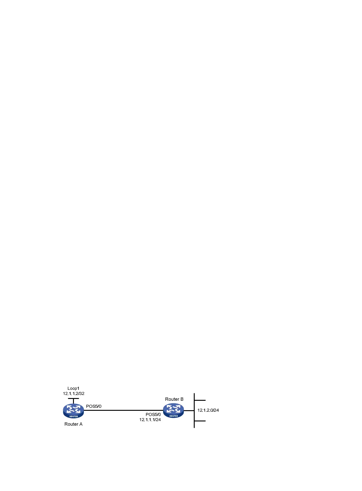
As shown in Figure 74, Router A and Router B are connected through their POS ports with HDLC
enabled.
Configure POS 5/0 of Router A to borrow the IP address of the local loopback interface, whose IP
address has a 32-bit mask.
Configure Router A to learn the routing information of Router B through static routes, so that Router
A can reach the network segment 12.1.2.0/24.
Figure 74 Network diagram

 Loading...


