241
[LSW-Ethernet1/0] port trunk permit vlan 2
DLSw v2.0 configuration example
Network requirements
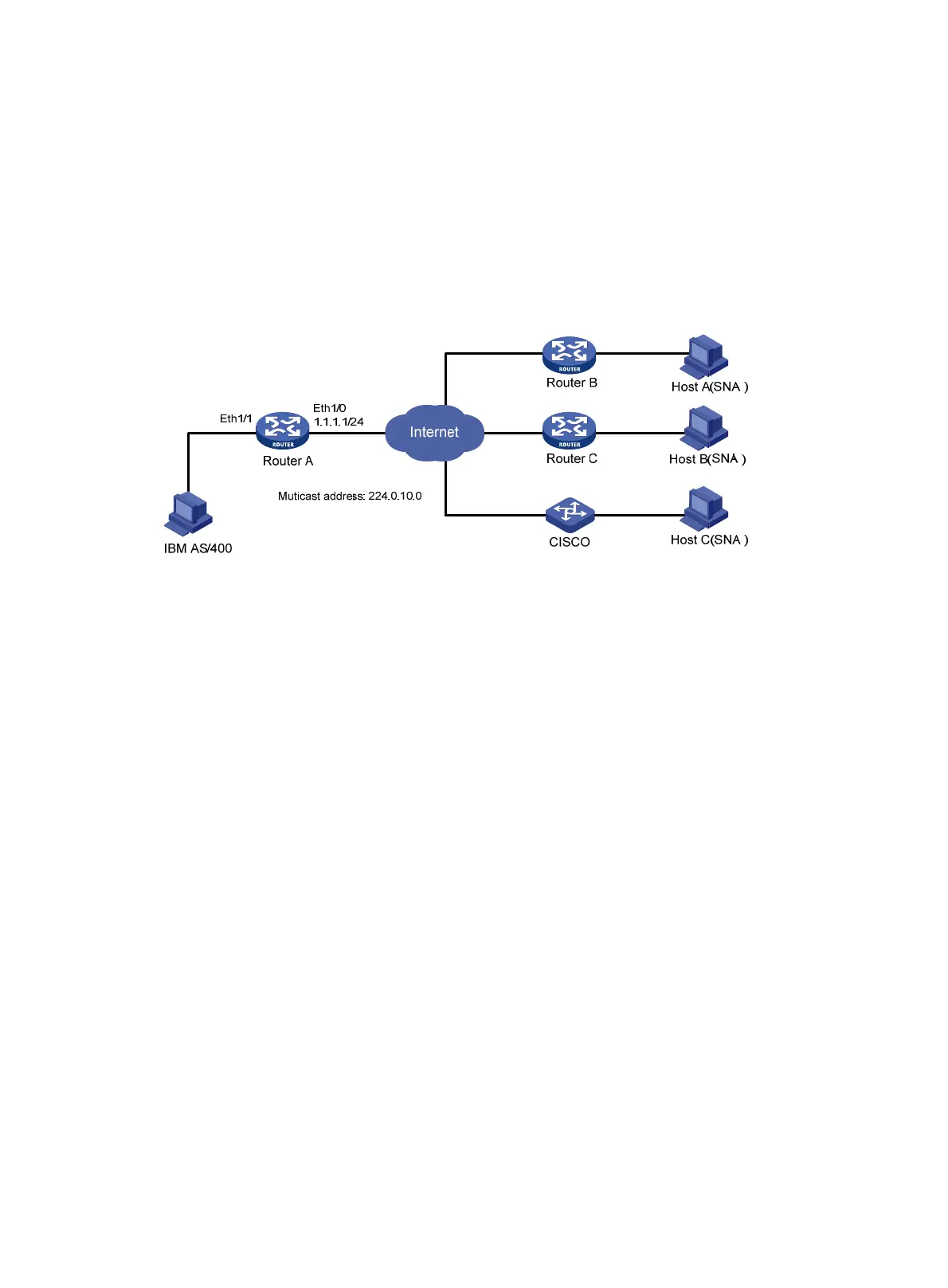
As shown in Figure 81, Router A is DLSw v2.0 capable, connected with an IBM host. Router B and
Router C are DLSw v1.0 or DLSw v2.0 capable, connected with PC1 and PC2, respectively. CISCO
is a DLSw-capable router of Cisco, connected with PC3. All the DLSw routers listen to the multicast
address 224.0.10.0. Enable the IBM host to communicate with all SNA hosts.
Figure 81 Network diagram
Configuration procedure
1. Configure Router A:
# Configure bridge set 1.
<RouterA> system-view
[RouterA] bridge enable
[RouterA] bridge 1 enable
# Add Ethernet 1/1 to bridge set 1.
[RouterA] interface ethernet 1/1
[RouterA-Ethernet1/1] bridge-set 1
[RouterA-Ethernet1/1] quit
# Enable multicast.
[RouterA] multicast routing-enable
[RouterA] interface ethernet 1/0
[RouterA-Ethernet1/0] pim dm
[RouterA-Ethernet1/0] igmp enable
[RouterA-Ethernet1/0] igmp static-group 224.0.10.0
[RouterA-Ethernet1/0] quit
# Configure local DLSw peers, and allow a remote peer that is not preconfigured to initiate a
TCP connection and establish dynamic peer relationship.
[RouterA] dlsw local 1.1.1.1 permit-dynamic
# Enable DLSw multicast, set the maximum number of explorer retries and specify a local
bridge set.
[RouterA] dlsw multicast interface ethernet 1/0
[RouterA] dlsw max-transmission 3
[RouterA] dlsw bridge-set 1
2. Configure Router B and Router C:

 Loading...


