207
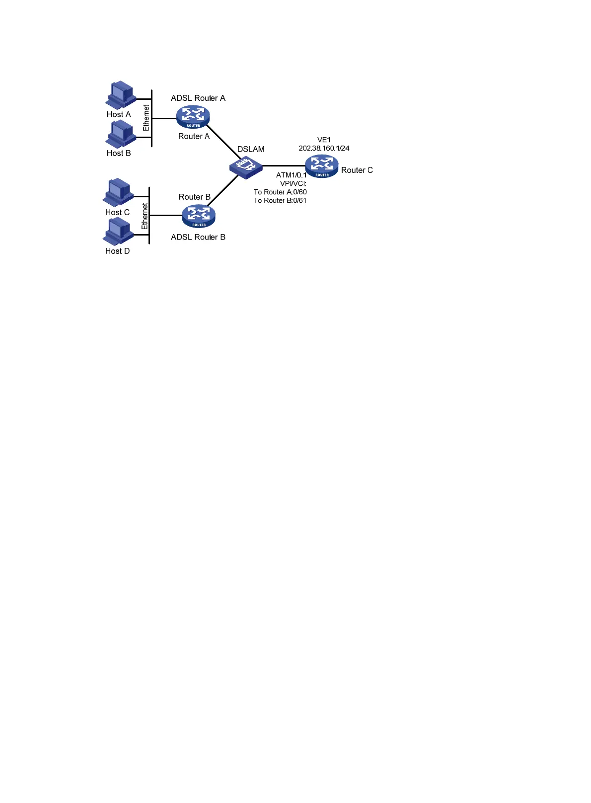
Figure 68 Network diagram
Configuration procedure
Configure Router C:
# Create a VE interface and configure an IP address for it.
<RouterC> system-view
[RouterC] interface virtual-ethernet 1
[RouterC-Virtual-Ethernet1] ip address 202.38.160.1 255.255.255.0
[RouterC-Virtual-Ethernet1] quit
# Create a PVC and enable IPoEoA on it.
[RouterC] interface atm 1/0.1
[RouterC-Atm1/0.1] pvc to_adsl_a 0/60
[RouterC-atm-pvc-Atm1/0.1-0/60-to_adsl_a] map bridge virtual-ethernet 1
[RouterC-atm-pvc-Atm1/0.1-0/60-to_adsl_a] quit
[RouterC-Atm1/0.1] pvc to_adsl_b 0/61
[RouterC-atm-pvc-Atm1/0.1-0/61-to_adsl_b] map bridge virtual-ethernet 1
PPPoA configuration example
Network requirements
As shown in Figure 69, two hosts dial into the ATM network each through an ADSL Router, and
communicate with Router C through DSLAM. The requirements are as follows:
• To create VT for multiuser on Router C, and configure PPP mapping on VT.
The VPI/VCI value of two PVCs connecting Router C and DSLAM are 0/60 and 0/61, pointing to
ADSL Router A and ADSL Router B, respectively.
• Both the WAN port of Router C and the DSL interfaces of the two ADSL routers adopt PPPoA.
The authentication mode of ADSL Router is PAP. The IP addresses of the two ADSL Routers
are assigned by Router C.
 Loading...


