351
[Router] interface serial 2/0
[Router-Serial2/0] link-protocol x25
[Router-Serial2/0] x25 vc-range in-channel 9 16 bi-channel 17 1024
[Router-Serial2/0] shutdown
[Router-Serial2/0] undo shutdown
Verifying the configuration
# Display the configuration of interface Serial2/0.
[Router-Serial2/0] display this
#
interface Serial2/0
link-protocol x25
x25 vc-range in-channel 9 16 bi-channel 17 1024
#
return
Transmitting IP datagrams through X.25 PVCs
Network requirements
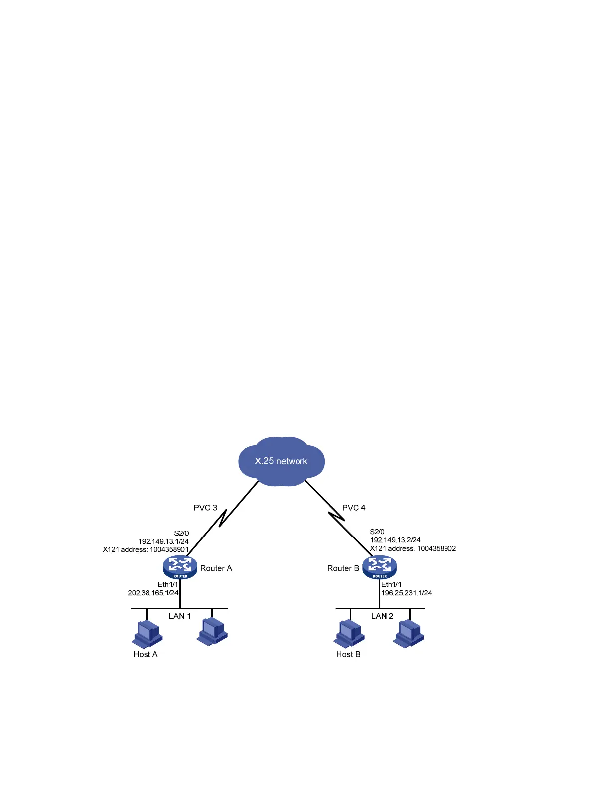
As shown in Figure 139,
• The PVC range that the packet network allows is [1, 8]. The PVC numbers assigned to Router A
and Router B are 3 and 4.
• The IP addresses of LAN 1 and LAN 2 are 202.38.165.0/24 and 196.25.231.0/24.
Exchange route information between LAN 1 and LAN 2 by using RIP, so that Host A and Host B can
exchange information without any static route.
Figure 139 Network diagram
Configuration procedure
1. Configure Router A:
# Configure interface Ethernet 1/1.
<RouterA> system-view

 Loading...


