237
[RouterB] bridge enable
[RouterB] bridge 7 enable
[RouterB] dlsw local 2.2.2.2
[RouterB] dlsw remote 1.1.1.1
[RouterB] dlsw bridge-set 7
[RouterB] interface ethernet 1/0
[RouterB-Ethernet1/0] bridge-set 7
After this configuration, the two SNA LANs across the Internet are interconnected.
Configuring SDLC-to-SDLC DLSw
Network requirements
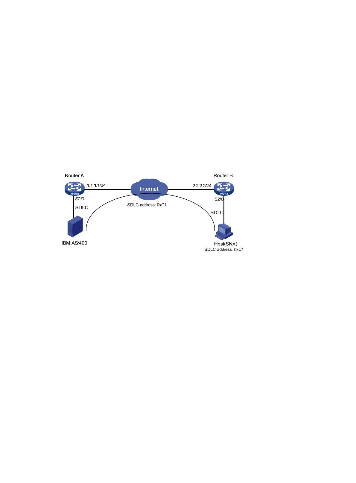
As shown in Figure 78, DLSw works in an SDLC-to-SDLC environment. Configure DLSw on Router A
and Router B to enable communication between the two SDLC LANs over the Internet.
Figure 78 Network diagram
Configuration procedure
1. Configure Router A:
Configure interfaces on Router A to make sure that the local DLSw peer 1.1.1.1 and remote
peer 2.2.2.2 can reach each other. (Details not shown.)
# Configure DLSw on Router A.
<RouterA> system-view
[RouterA] dlsw local 1.1.1.1
[RouterA] dlsw remote 2.2.2.2
[RouterA] interface serial 2/0
[RouterA-Serial2/0] link-protocol sdlc
[RouterA-Serial2/0] sdlc enable dlsw
[RouterA-Serial2/0] sdlc status secondary
[RouterA-Serial2/0] sdlc controller c1
[RouterA-Serial2/0] sdlc mac-map remote 0000-2222-00c1 c1
[RouterA-Serial2/0] sdlc mac-map local 0000-1111-0000
[RouterA-Serial2/0] baudrate 9600
[RouterA-Serial2/0] code nrzi
2. Configure Router B:
Configure interfaces on Router B to make sure that the local DLSw peer 2.2.2.2 and remote
peer 1.1.1.1 can reach each other (Details not shown.)
# Configure DLSw on Router B.

 Loading...


