250
SAP address-based filtering configuration example
Network requirements
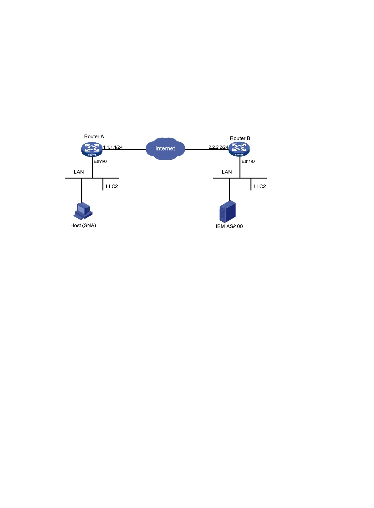
As shown in Figure 87:
• DLSw operates in LAN-to-LAN mode.
• Configure DLSw on Router A and Router B to connect the IBM host with the SNA host through
the Internet.
• Configure SAP-rule-based ACLs on Router A to filter the packets sent to the remote peer.
Figure 87 Network diagram
Configuration procedures
1. Configure Router A:
# Configure interfaces on Router A to make sure that the local DLSw peer 1.1.1.1 and remote
peer 2.2.2.2 can reach each other. (Details not shown.)
# Configure DLSw on Router A.
<RouterA> system-view
[RouterA] acl number 4000
[RouterA-acl-ethernetframe-4000] rule deny lsap 0404 ffff
[RouterA-acl-ethernetframe-4000] rule permit
[RouterA-acl-ethernetframe-4000] quit
[RouterA] bridge enable
[RouterA] bridge 5 enable
[RouterA] dlsw local 1.1.1.1
[RouterA] dlsw remote 2.2.2.2 lsap-output-acl 4000
[RouterA] dlsw bridge-set 5
[RouterA] interface ethernet 1/0
[RouterA-Ethernet1/0] bridge-set 5
2. Configure Router B:
# Configure interfaces on Router B to make sure that the local DLSw peer 2.2.2.2 and remote
peer 1.1.1.1 can reach each other. (Details not shown.)
# Configure DLSw on Router B.
<RouterB> system-view
[RouterB] bridge enable
[RouterB] bridge 7 enable
[RouterB] dlsw local 2.2.2.2

 Loading...


