85
Configuring frame relay
The MSR 900 routers do not support frame relay. Of the MSR93X series routers, only the JG514A,
JG514B, JG515A, JG531A and JG531B routers support frame relay.
Overview
Frame relay is essentially simplified X.25 WAN technology. It uses statistical multiplexing technology
and can establish multiple virtual circuits over a single physical cable to make full use of network
bandwidth. Frame relay uses data link connection identifiers (DLCIs) to identify virtual circuits and
maintain the status of each virtual circuit with the Local Management Interface (LMI) protocol.
Frame relay interface types
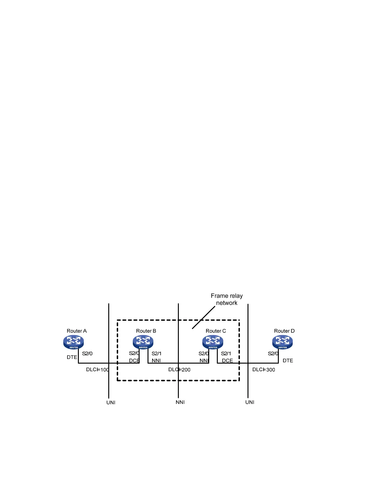
As shown in Figure 23, frame relay enables communication between user devices such as routers
and hosts. The user devices are also called "data terminal equipment (DTE)." They are connected to
a frame relay network through the DTE interface. The devices that provide access to the frame relay
network for DTEs are called "data communications equipment (DCE)." A DCE is connected to a DTE
with a DCE interface on the user network interface (UNI) side and to a frame relay switch in the frame
relay network with a network-to-network interface (NNI) on the NNI side. The switches in the frame
relay cloud are interconnected with the NNI.
In actual applications, a DTE interface can connect to only a DCE interface, and an NNI interface can
connect to only an NNI interface. On a frame relay switch, the frame relay interface should be an NNI
or DCE interface.
As shown in Figure 23, Ro
uter B and Router C form a simple frame relay network, to which DTE
devices Router A and Router D are attached. The DTE and DCE are identified on only the UNI
interface; a virtual circuit between two DTE devices can be assigned different DLCIs on different
segments.
Figure 23 Example frame relay network
Virtual circuit
Virtual circuits are logical paths established between two devices. Depending on how they are set up,
virtual circuits include the following types:

 Loading...


