358
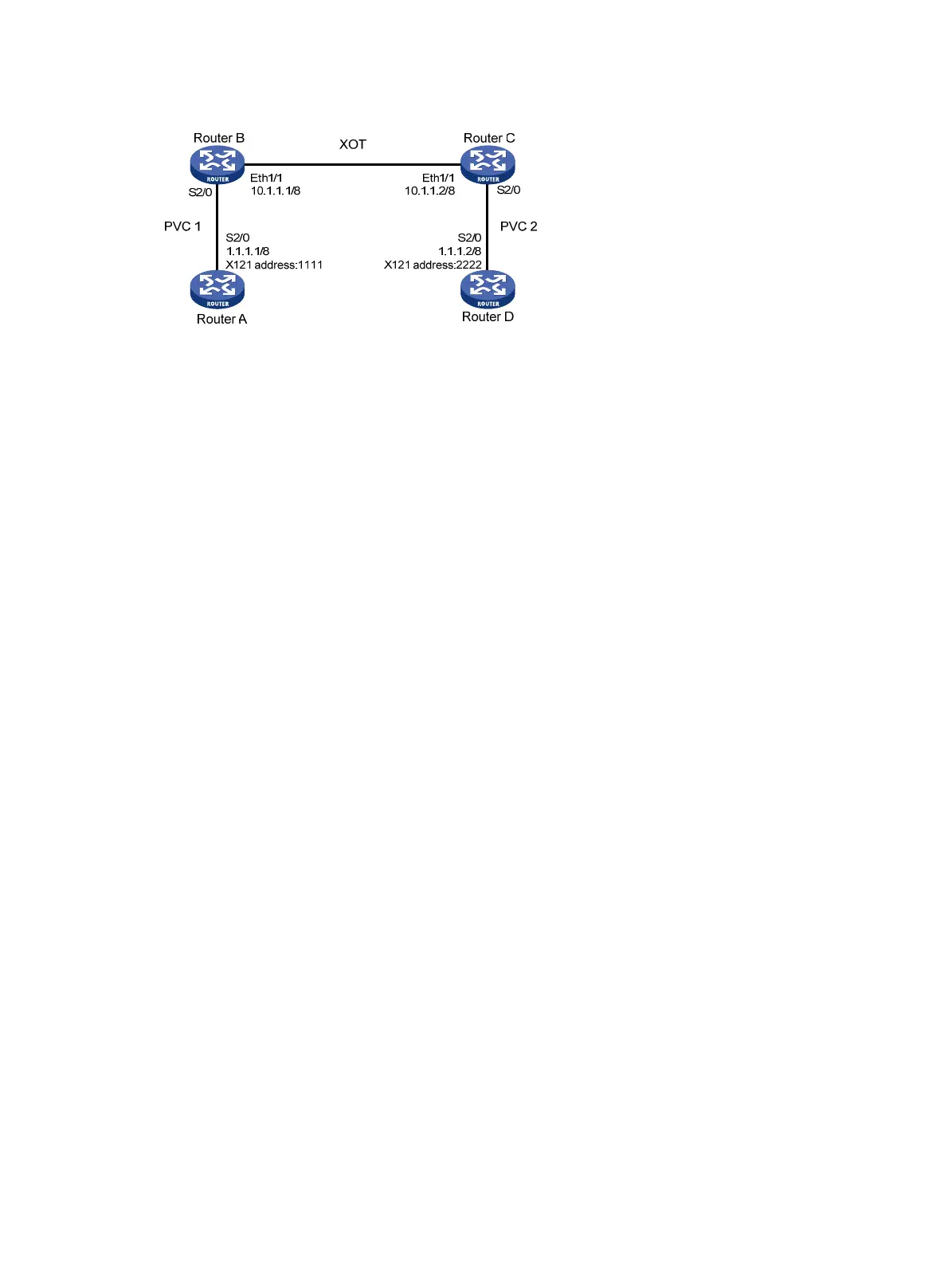
Figure 143 Network diagram
Configuration procedure
1. Configure Router A:
# Configure basic X.25.
<RouterA> system-view
[RouterA] interface serial 2/0
[RouterA-Serial2/0] link-protocol x25 dte ietf
[RouterA-Serial2/0] x25 x121-address 1111
[RouterA-Serial2/0] x25 vc-range in-channel 10 20 bi-channel 30 1024
[RouterA-Serial2/0] x25 pvc 1 ip 1.1.1.2 x121-address 2222
[RouterA-Serial2/0] ip address 1.1.1.1 255.0.0.0
2. Configure Router D:
# Configure basic X.25.
<RouterD> system-view
[RouterD] interface serial 2/0
[RouterD-Serial2/0] link-protocol x25 dte ietf
[RouterD-Serial2/0] x25 x121-address 2222
[RouterD-Serial2/0] x25 vc-range in-channel 10 20 bi-channel 30 1024
[RouterD-Serial2/0] x25 pvc 2 ip 1.1.1.1 x121-address 1111
[RouterD-Serial2/0] ip address 1.1.1.2 255.0.0.0
3. Configure Router B:
# Enable X.25 switching.
<RouterB> system-view
[RouterB] x25 switching
# Configure Serial 2/0 and an XOT route.
[RouterB] interface serial 2/0
[RouterB-Serial2/0] link-protocol x25 dce ietf
[RouterB-Serial2/0] x25 vc-range in-channel 10 20 bi-channel 30 1024
[RouterB-Serial2/0] x25 xot pvc 1 10.1.1.2 interface serial 2/0 pvc 2
# Configure Ethernet 1/1.
[RouterB] interface ethernet 1/1
[RouterB-Ethernet1/1] ip address 10.1.1.1 255.0.0.0
4. Configure Router C:
# Enable X.25 switching.
<RouterC> system-view
[RouterC] x25 switching

 Loading...


