215676 428 Revision A
3. Move the platform on the left cab-forward side of the machine to the open position. For instructions, refer to 5.4.1
Opening Platforms – Standard Position, page 319.
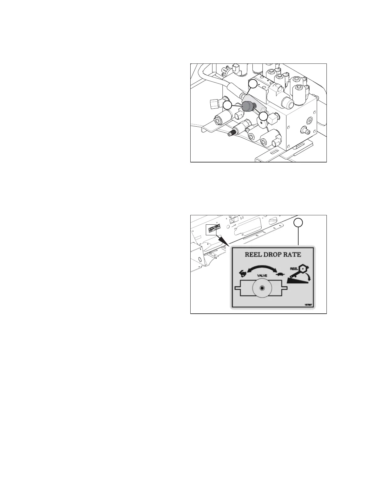
Figure 5.196: Multifunction Control Manifold
4. Locate drop rate control valve (A), installed at port D on the
manifold.
NOTE:
This valve is installed on draper-ready windrowers; it affects
draper headers only.
5. Loosen set screw (B). Turn cap (C) as follows:
• Turn cap (C) clockwise to decrease the reel drop rate.
• Turn cap (C) counterclockwise to increase the reel
drop rate.
6. Check the reel drop rate. Repeat this procedure as needed.
NOTE:
To reset the drop rate to factory specifications, fully close
the needle valve and then open it four turns
counterclockwise.
7. Tighten set screw (B).
Figure 5.197: Reel Drop Rate Decal
NOTE:
Refer to reel drop rate decal (A) for information on how
changing the valve position affects the reel’s drop rate.
8. Close the platform. For instructions, refer to 5.4.2 Closing
Platforms – Standard Position, page 320.
5.11.6 Traction Drive Hydraulics
The windrower transmission consists of two variable-displacement axial-piston hydraulic pumps; each drive wheel has its
own dedicated pump.
The pumps are driven through a gearbox from the engine. Each pump requires charge flow in order to:
• Compensate for internal hydraulic fluid leakage
• Maintain positive pressure in the main circuit
• Maintain the temperature of the hydraulic system
• Compensate for leakage losses from the external valving or auxiliary systems
The windrower control module (WCM) monitors the charge pressure. The cab display module (CDM) will emit a tone and
display a flashing warning message if the charge pressure drops below 1725 kPa (250 psi). For more information, refer to
Display Warnings and Alarms, page 82.
MAINTENANCE AND SERVICING