BASIC SYSTEM
U–19
U
U
HEATER AND AIR CONDITIONER SYSTEMS
.
BASIC SYSTEM
9
8
7
5
4
10
19
18
17
15
16
14
13
12
20
29
28
25
26
23
21
22
30
35
33
31
32
6
1
2
34
18
16
14
13
MANUAL AIR
CONDITIONER
FULL-AUTO
AIR CONDITIONER
R.H.D.
TYPE C
3.5—5.5
{36—56,
31—48}
N·m {kgf·cm, in·lbf}
R
R
11
15
PLATE
R
R
24
27
B6E8516W006
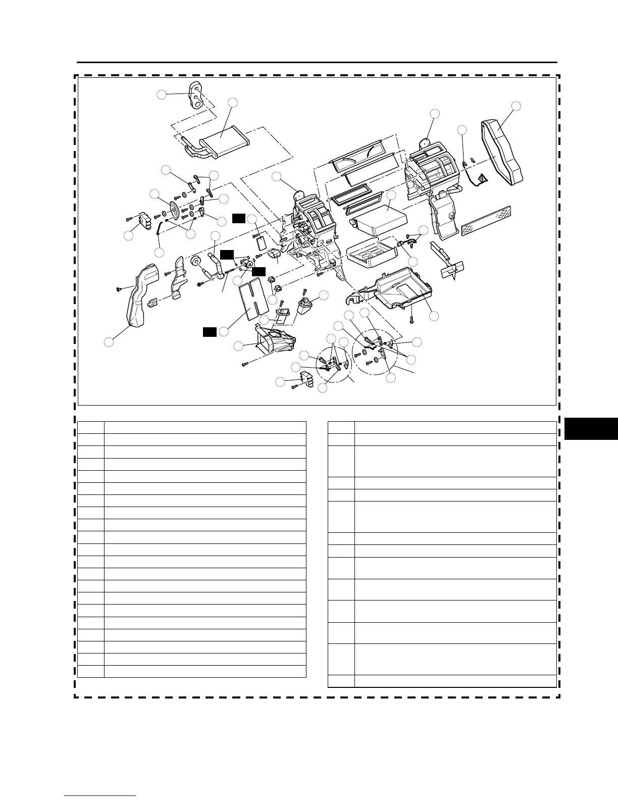
1Duct (1)
2 Polyurethane protector (1)
3 Polyurethane protector (2) (R.H.D., L.H.D. type C)
4 Airflow mode actuator (full-auto air conditioner)
5 Airflow mode rod (manual air conditioner)
6 Airflow mode main link
7 Airflow mode sub link (1) (manual air conditioner)
8 Airflow mode sub link (2)
9 Airflow mode sub link (3)
10 Airflow mode crank
11 Airflow mode rod holder (manual air conditioner)
12 Air mix actuator (full-auto air conditioner)
13 Air mix rod
14 Air mix crank (1)
15 Air mix link (1)
16 Air mix crank (2)
17 Air mix link (2) (manual air conditioner)
18 Air mix rod holder
19 Wire clamp (manual air conditioner)
20 Heater core
21 Resistor (manual air conditioner)
22 Power MOS FET (full-auto air conditioner)
23 Duct (2)
24 Adhesive polyurethane (1)
(See U–20–2 Adhesive polyurethane (1) Assembly
Note)
25 Outlet pipe
26 Expansion valve
27 Adhesive polyurethane (2)
(See U–20–1 Adhesive polyurethane (2) Assembly
Note)
28 Duct (3)
29 Water temperature sensor (full-auto air conditioner)
30 A/C case (3)
(See U–20 A/C Case Assembly Note)
31 A/C case (1)
(See U–20 A/C Case Assembly Note)
32 A/C case (2)
(See U–20 A/C Case Assembly Note)
33 Sensor clamp
(See U–20 Sensor Clamp Assembly Note)
34 Evaporator temperature sensor
(See U–20 Evaporator Temperature Sensor
Assembly Note)
35 Evaporator