U–20
BASIC SYSTEM
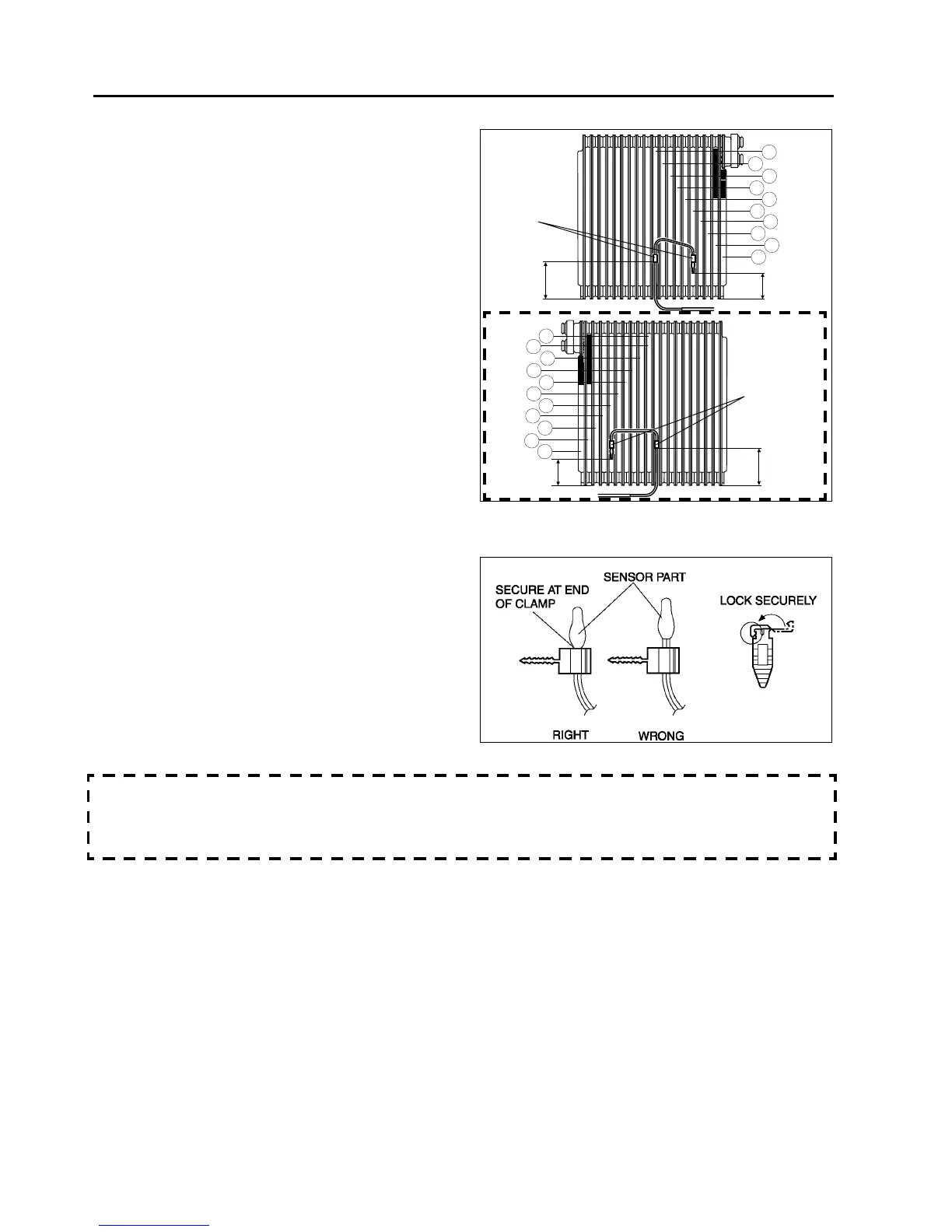
Evaporator Temperature Sensor Assembly Note
1. Assemble the evaporator temperature sensor as
shown in the figure.
Sensor Clamp Assembly Note
1. Attach the sensor clamp as shown in the figure.
A/C Case Assembly Note
• Before assembling the A/C case, apply sealant (one-component, non-solvent, non-alcohol type) to the groove
along the joint where A/C case (1) and A/C case (3) are joined. Make sure to apply sealant completely around
the whole periphery of the joint, and that there are no gaps.
End Of Sie
35—45 mm
{1.4—1.7 in}
L.H.D.
5
4
3
1
2
55—65 mm
{2.2—2.5 in}
SENSOR
CLAMP
9
8
7
10
6
R.H.D.
SENSOR
CLAMP
35—45 mm
{1.4—1.7 in}
47—57 mm
{1.9—2.2 in}
5
4
3
1
2
9
8
7
10
6
11
B6E8516W007
A6E8516W007



 To Next Page