11 PROCESS CONTROL INSTRUCTIONS
11.2 I/O Control Instructions
1211
11
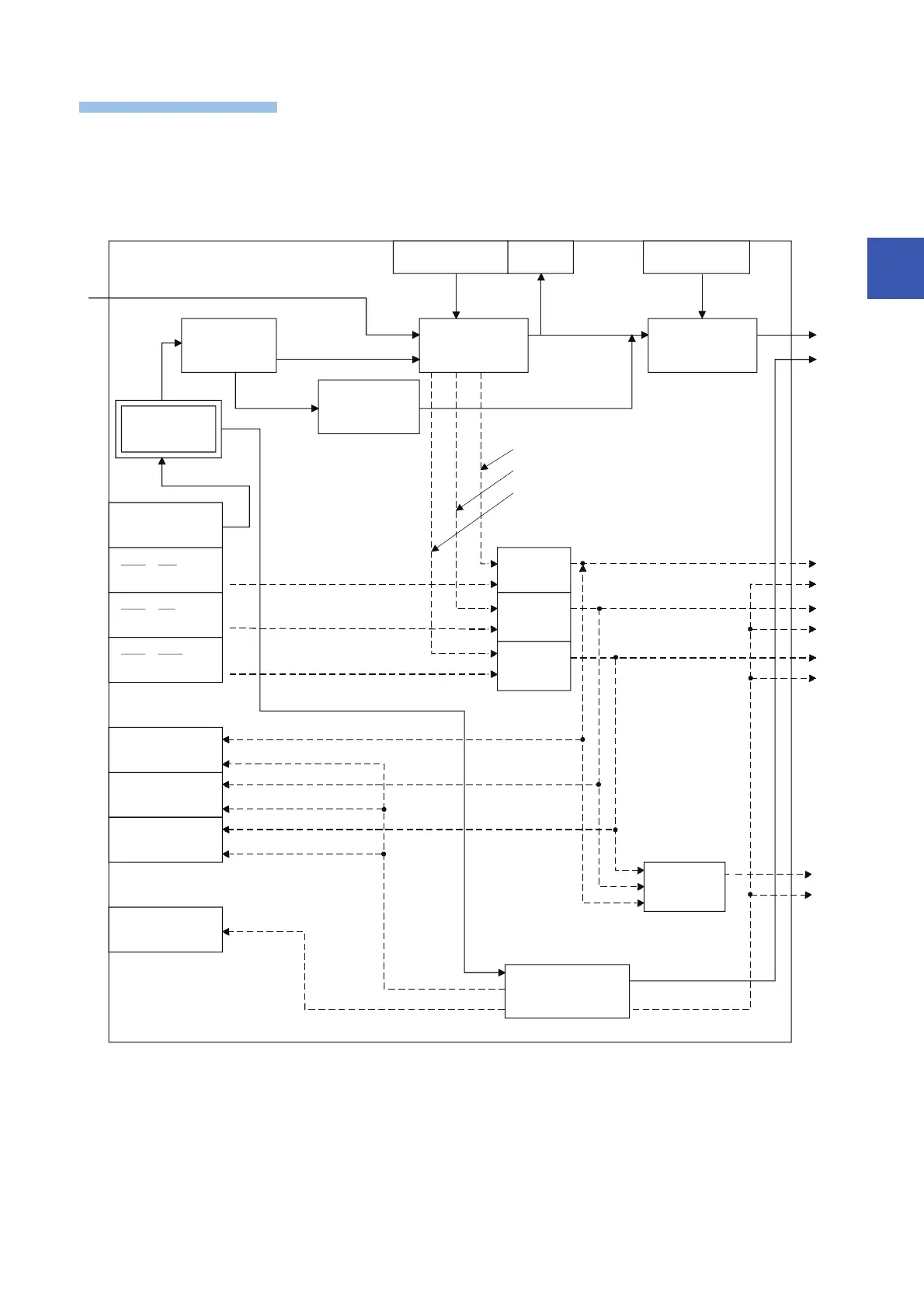
This instruction performs output conversion of the input value (E1=MV) in the device specified by (s1), and stores the result in
the device specified by (d1). The instruction also performs variation rate & upper/lower limiter and output conversion
processing of the input value at that time.
The following is the processing block diagram of the S.OUT2 instruction. (The numbers (1) to (4) in the diagram indicate the
order of the processing.)
BW
BB2
BB3
BB1
BB4
MODE
SPA
ERRI¸MLI
ERRI¸MHI
ERRI¸DMLI
MHA
MLA
DMLA
AND
AND
AND
OR
MAN
(4)
E1
(1)
(2) (3)
(4)
MH, ML, DML
NMAX, NMIN
MV
Mode
determination
Other than
MAN, CMB, CMV, LCM
MAN, CMB,
CMV, LCM
Variation rate,
upper/lower
limiter
Output
conversion
Loop stop
determination
RUN (SPA=0)
STOP (SPA=1)
Alarm clear
Upper limit alarm
Lower limit alarm
Variation rate alarm
OFF (all bits)
OFF (all bits)
Loop stop
processing
BW=Last value

 Loading...


