4 - 20
4. HOW TO MONITOR REDUNTANT SYSTEM
4.4 CC-Link Connection (Via G4)
4.4 CC-Link Connection (Via G4)
This section explains the CC-Link connection (via G4) that connects the GOT to the AJ65BT-G4-S3 of the CC-Link
network.
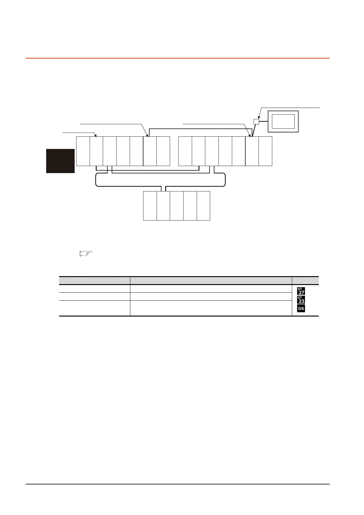
The following shows an example of connecting the GOT to the AJ65BT-G4-S3 of the CC-Link network.
(1) Connection method
Connect the AJ65BT-G4-S3 of the CC-Link network to the GOT.
For details, refer to the following.
13. CC-Link CONNECTION (Via G4)
(2) GT Designer3 setting
Set GT Designer3 as follows.
Setting item Settings Model
Controller Type MELSEC-QnA, MELDAS C6*
Device setting (Network setting) Host
Q Redundant Setting Do not set the item.
Monitor target
Power supply
module
MELSECNET/H remote I/O network
GOT
Network No. 0, Station No. 0
(Master station)
Control
system
(System A)
Empty
Q25PRHCPU
QJ71LP21-25
QJ71BR11
QJ71E71-100
QJ61BT11N
Empty
Standby system
(System B)
Q25PRHCPU
QJ71LP21-25
QJ71BR11
QJ71E71-100
QJ61BT11N
QJ72LP25-25
QJ71C24N
CC-Link
Network No. 0, Station No. 1
(Standby master station)
Network No. 0, Station No. 2
(AJ65BT-G4-S3)
Power supply
module
Power supply
module
Empty
Empty

 Loading...


