5. ETHERNET CONNECTION
5.4 PLC Side Setting
5 - 43
5
ETHERNET CONNECTION
Confirming the communication state of
Ethernet module
(1) When using the Command Prompt of Windows
.
Execute a Ping command at the Command Prompt of
Windows
.
(a) When normal communication
C:\>Ping 192.168.3.19
Reply from 192.168.3.19: bytes=32 time<1ms
TTL=64
(b) When abnormal communication
C:\>Ping 192.168.3.19
Request timed out.
(2) When abnormal communication
At abnormal communication, check the followings and
execute the Ping command again.
• Mounting condition of Ethernet communication unit
• Cable connecting condition
• Confirmation of switch and network parameter setting
• Operation state of PLC CPU (faulty or not)
• IP address of GOT specified by Ping command
5.4.9 Connecting to Display I/F
(CNC C70)
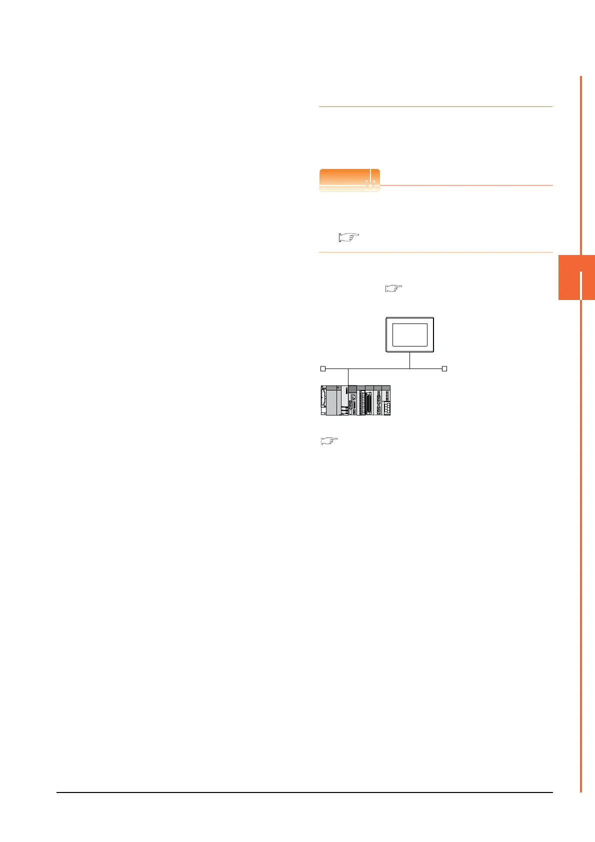
This section describes the settings of the GOT and Display
I/F (CNC C70) in the following case of the system
configuration.
Display I/F (CNC C70)
For details of the Display I/F (CNC C70), refer to the
following manual.
C70 Series SET UP MANUAL
System configuration
<GOT> (The settings other than the
following are set to the default)
Network No. : 1
PLC No. : 1
IP address : 192.168.3.18
Port No. : 5001
Communication format : UDP (fixed)
Network No. : 239
PLC No. : 2
IP address : 192.168.3.19
Port No. : 5001
Communication format
: UDP(fixed)
<Q17nNCCPU> (The settings other than the
following are set to the default)
[Controller Setting] and [Ethernet] of GT
Designer3
■
■ IP address settings of CNC C70

 Loading...


