5 - 18
5. ETHERNET CONNECTION
5.4 PLC Side Setting
5.4 PLC Side Setting
5.4.1 Connecting to Built-in
Ethernet port CPU (one-to-
one connection)
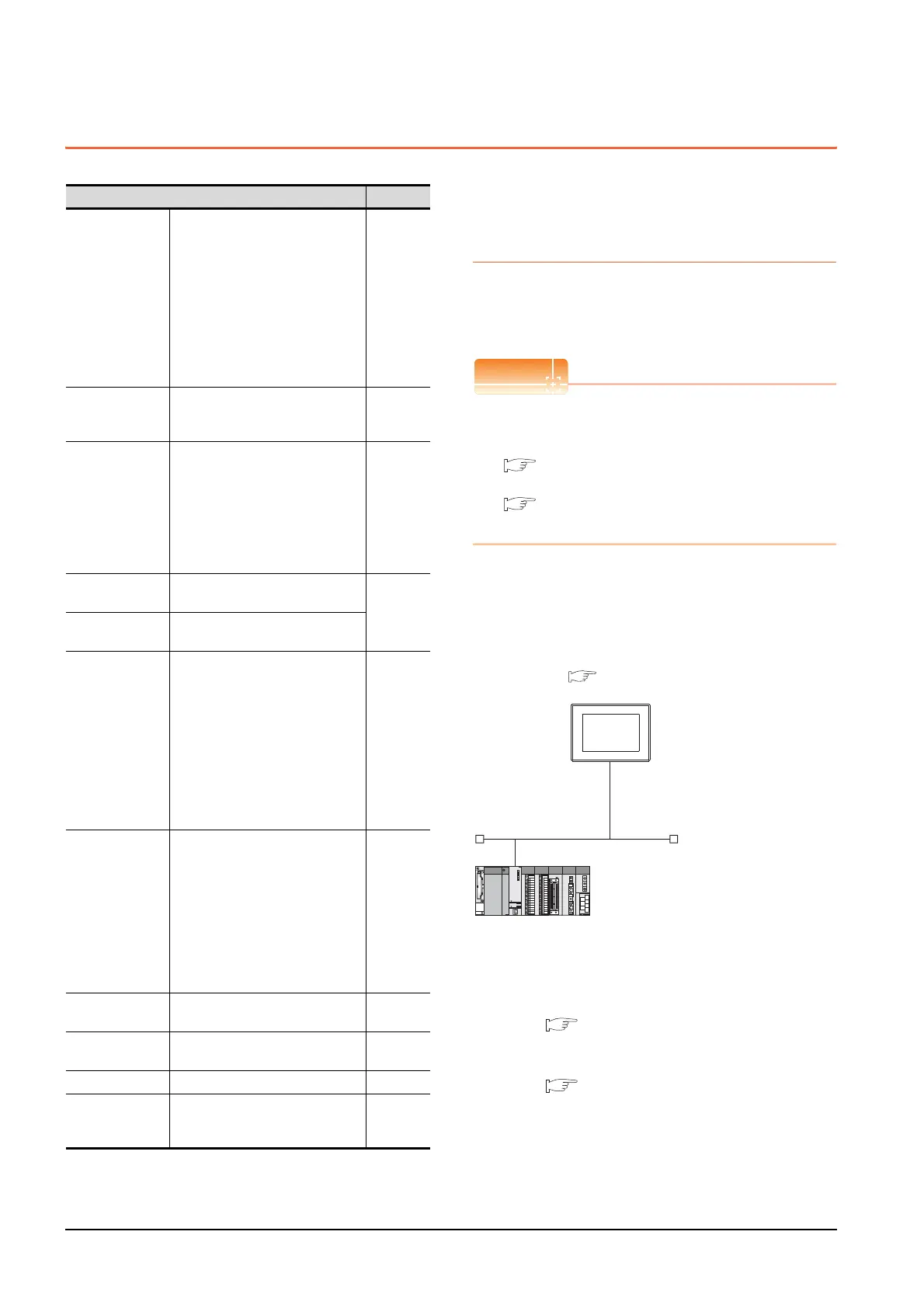
This section describes the settings of the GOT and Built-in
Ethernet port CPU in the following case of system
configuration.
Connecting to Built-in Ethernet port CPU
For details of Built-in Ethernet port CPU, refer to the
following manual.
QnUCPU User's Manual (Communication via
Built-in Ethernet Port)
MELSEC-L CPU Module User's Manual (Built-
In Ethernet Function)
System configuration
For connecting one Built-in Ethernet port QCPU to one
GOT, the PLC side settings are not required. Set
[Ethernet] for [Controller Setting] on GT Designer3, and
then connect Built-in Ethernet port QCPU to the GOT.
*1 For the settings when using system devices including a hub
and a transceiver, refer to the following.
5.4.2 Connecting to Built-in Ethernet port CPU
(multiple connection)
*2 These setting items do not exist at the PLC side. However,
the virtual values must be set on the GOT side.
[Controller Setting] and [Ethernet] of GT Designer3
Model Reference
Built-in Ethernet
port QCPU
Q03UDECPU, Q04UDEHCPU,
Q06UDEHCPU, Q10UDEHCPU,
Q13UDEHCPU, Q20UDEHCPU,
Q26UDEHCPU, Q50UDEHCPU,
Q100UDEHCPU, Q03UDVCPU,
Q04UDVCPU, Q06UDVCPU,
Q13UDVCPU, Q26UDVCPU,
Q172DSCPU, Q173DSCPU,
Q172DCPU-S1, Q173DCPU-S1,
Q170MCPU,
Q170MSCPU, Q170MSCPU-S1
5.4.1
5.4.2
5.4.11
C Controller
module
Q12DCCPU-V
Q24DHCCPU-V
Q24DHCCPU-LS
5.4.4
Built-in Ethernet
port LCPU
L02CPU
L26CPU
L26CPU-BT
L02CPU-P
L06CPU-P
L26CPU-P
L26CPU-PBT
L06CPU
5.4.1
5.4.2
Ethernet module
(Q Series)
QJ71E71-100, QJ71E71-B5,
QJ71E71-B2, QJ71E71
5.4.3
Ethernet module
(L Series)
LJ71E71-100
Ethernet module
(QnA Series)
AJ71QE71N3-T,
AJ71QE71N-B5,
AJ71QE71N-B2, AJ71QE71N-T,
AJ71QE71N-B5T,
AJ71QE71, AJ71QE71-B5,
A1SJ71QE71N3-T,
A1SJ71QE71N-B5,
A1SJ71QE71N-B2, A1SJ71QE71N-T,
A1SJ71QE71N-B5T,
A1SJ71QE71-B5,
A1SJ71QE71-B2
5.4.5
Ethernet module
(A Series)
AJ71E71N3-T, AJ71E71N-B5,
AJ71E71N-B2, AJ71E71N-T,
AJ71E71N-B5T, AJ71E71-S3,
A1SJ71E71N3-T,
A1SJ71E71N-B5,
A1SJ71E71N-B2,
A1SJ71E71N-T,
A1SJ71E71N-B5T,
A1SJ71E71-B5-S3,
A1SJ71E71-B2-S3
5.4.6
Ethernet module
(FX Series)
FX
3U-ENET-L, FX3U-ENET-ADP 5.4.7
Built-in Ethernet
port FXCPU
FX
3GE 5.4.8
CNC C70 Q173NCCPU 5.4.9
CC-Link IE Field
Network Ethernet
Adapter Module
QJ71GF11-T2 5.4.10
<GOT>
(The settings other than the
following are set to the default)
*1
*2
*2
Network No.
: 1
PLC No. : 1
IP address
: 192.168.3.18
Port No.
: 5001
Communication
format
: UDP (fixed)
Network No.
: 1 (virtual)
PLC No.
: 2 (virtual)
IP address
: 192.168.3.39
Port No.
: 5006 (fixed)
Communication
format
: UDP (fixed)
<Connecting to Built-in Ethernet port CPU>
(The following settings are set to the default)
[Controller Setting] and [Ethernet] of GT
Designer3
■

 Loading...


