4 - 24
4. HOW TO MONITOR REDUNTANT SYSTEM
4.7 Ethernet Connection
4.7 Ethernet Connection
This section explains the Ethernet connection that connects the GOT to the Ethernet network system.
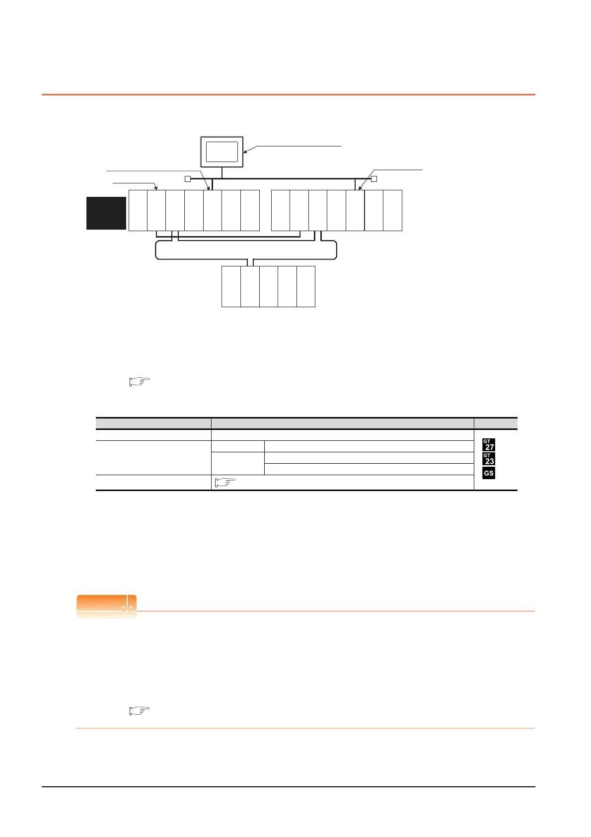
The following shows an example of connecting the GOT to the Ethernet network.
(1) Connection method
Connect the Ethernet network system to the GOT.
Set the Ethernet modules of System A and System B (including NW No., station No, and IP address) to the
Ethernet setting of the GOT side.
For details, refer to the following.
5. ETHERNET CONNECTION
(2) GT Designer3 setting
Set GT Designer3 as follows.
To specify the station number which was set in the Q redundant setting in the device setting, set the station
number as the other station.
(3) Monitoring target change when system switching occurs in a redundant system
When system switching occurs, Ethernet module station No. 2 takes over the control of the Ethernet network
system as the control system.
Since the GOT monitors the control system, he monitoring target is automatically changed to the Ethernet
module station No. 2.
When monitoring control system without Q redundant setting
When system switching occurs, Ethernet module station No. 2 takes over the control of the Ethernet network
system as the control system.
Since the GOT monitors the station of the specified station number, the monitoring target cannot be changed to the
station No. 2 in response to the system switching.
As a countermeasure, create a screen to monitor the PLC CPU of the control system by switching the station
numbers between System A and System B using the script function.
4.10 Switch the Monitor Target to the Control System Using the Script Function
Setting item Settings Model
Controller Type MELSEC-QnA, MELDAS C6*
Device setting (Network setting)
Host Host (The control system is monitored.)
Other
NW No.: Network No. of Ethernet
Station No.: Station number of the control system
Q Redundant Setting
4.9 Q Redundant Setting
Monitor target
MELSECNET/H remote I/O network
Power supply
module
Empt
y
GOT
Network No. 1, Station No. 1
Control
system
(System A)
Empt
y
Q25PRHCPU
QJ71LP21-25
QJ71BR11
QJ71E71-100
QJ61BT11N
Empt
y
Standby
system
(System B)
Q25PRHCPU
QJ71LP21-25
QJ71BR11
QJ71E71-100
QJ61BT11N
QJ72LP25-25
QJ71C24N
Network No. 1, Station No. 3
Network No. 1,
Station No. 2
Ethernet
Power supply
module
Power supply
module
Empt
y

 Loading...


