8. BUS CONNECTION
8.2 System Configuration
8 - 7
8
BUS CONNECTION
8.2 System Configuration
When "CONTROL BUS ERR" or "UNIT VERIFY ERR" occurs
It can be considered that noise due to a long bus connection cable causes a malfunction.
Check whether a signal line such as bus cable is placed near the equipment to operate. If the line is close to the
equipment, make a distance of 100mm or more from the equipment.
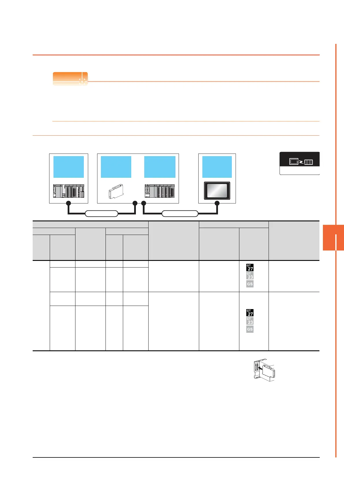
8.2.1 Connecting to QCPU
When one GOT is connected
*1 For the extension cables, refer to the MELSEC-Q catalog (L(NA)08032).
*2 When installing the GOT 13.2m or more away from the main base unit, the bus extension
connector box is required.
Attach the bus extension connector box to the extension connector of the base unit.
Also, connect the connection cable to the bus extension connector box.
When using no extension base unit: Attach it to the main base unit.
When using the extension base unit: Attach it to the extension base unit on the last stage.
*3 When using Q00JCPU or Q00UJCPU, attach the bus extension connector to the extension base unit. (Connecting it to the main
base unit is not allowed)
*4 When using the following functions, use GT15-QBUS(2). GT15-75QBUS(2)L cannot be used.
Remote personal computer operation (Serial), video display function, multimedia function, external I/O device, RGB display
function, sound output function
Extension base
unit
Bus extension
connector box
GOTMain base unit
Extension cable Connection cable
Communication driver
Bus(Q)
PLC
Connection cable
GOT
Max. distance
Main base
Extension
cable
*1
Extension base
Option device
*4
Model
Main
base
Bus
extension
connector
box
*2
Extens
ion
base
Bus
extension
connector
box
*2
Main
base
----
GT15-QC06B(0.6m)
GT15-QC12B(1.2m)
GT15-QC30B(3m)
GT15-QC50B(5m)
GT15-QC100B(10m)
GT15-75QBUSL
GT15-75QBUS2L
GT15-QBUS
GT15-QBUS2
Between main base and
GOT: 13.2m
(Including the extension
cable length)
-
Extension
cable
(13.2m or
less)
Extens
ion
base
-
A9GT
-QCNB
*3
---
GT15-QC06B(0.6m)
GT15-QC12B(1.2m)
GT15-QC30B(3m)
GT15-QC50B(5m)
GT15-QC100B(10m)
GT15-QC150BS(15m)
GT15-QC200BS(20m)
GT15-QC250BS(25m)
GT15-QC300BS(30m)
GT15-QC350BS(35m)
GT15-75QBUSL
GT15-75QBUS2L
GT15-QBUS
GT15-QBUS2
Between main base and
GOT: 37m
(Including the extension
cable length)
-
Extension
cable
(13.2m or
less)
Extens
ion
base
A9GT
-QCNB

 Loading...


