14. INVERTER CONNECTION
14.2 System Configuration
14 - 3
INVERTER CONNECTION
14
14.2 System Configuration
14.2.1 Connecting to FREQROL-A500/A500L/F500/F500L/V500/V500L
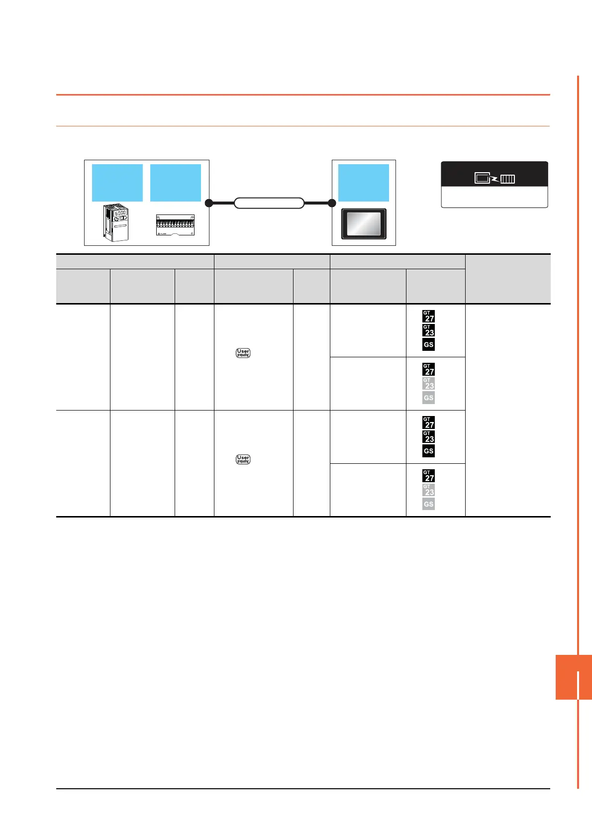
When connecting to one inverter
*1 Connect to the PU port of the inverter.
FREQROL 500/700/800,
SENSORLESS SERVO
Communication driver
GOT
Connection cable
Computer link
option
Inverter
Inverter Connection cable GOT
Number of connectable
equipment
Model name
Computer link
option
Communi
cation
type
Connection diagram
number
Max.
distance
Option device Model
FREQROL-
A500/A500L
F500/F500L
V500/V500L
*1
-RS-485
RS485
connection diagram 1)
500m
- (Built into GOT)
1 GOT for 1 inverter
GT15-RS4-9S
FREQROL-
A500/A500L
F500/F500L
V500/V500L
FR-A5NR RS-485
RS485
connection diagram 2)
500m
- (Built into GOT)
GT15-RS4-9S

 Loading...


