4. HOW TO MONITOR REDUNTANT SYSTEM
4.6 CC-Link IE Controller Network Connection (Network System)
4 - 23
4
HOW TO MONITOR REDUNTANT SYSTEM
4.6 CC-Link IE Controller Network Connection (Network
System)
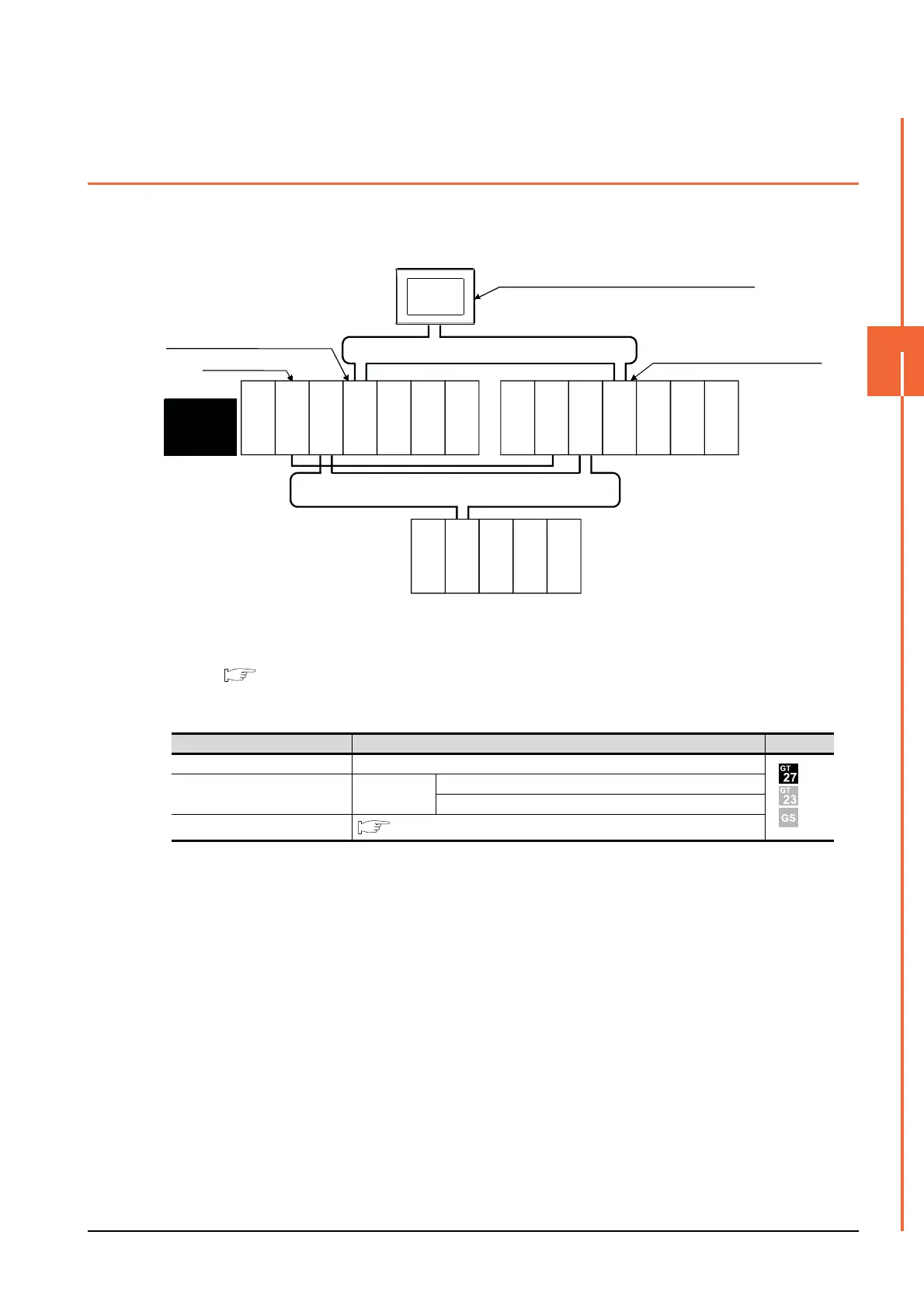
This section explains the CC-Link IE Controller Network connection (network system) that connects the GOT to the CC-
Link IE controller network.
The following shows an example of connecting the GOT set as a normal station to the CC-Link IE Controller Network.
(1) Connection method
Connect the GOT to the CC-Link IE Controller Network.
For details, refer to the following.
10. CC-Link IE CONTROLLER NETWORK CONNECTION
(2) GT Designer3 setting
Set GT Designer3 as described below.
To specify the station number which was set in the Q redundant setting in the device setting, set the station
number as the other station.
(3) Monitoring target change when system switching occurs in a redundant system
When system switching occurs, the network module station No.2 changes from a normal station to the sub
control station, and the system with the module takes over the control of the CC-Link IE Controller Network as
the control system.
Since the GOT monitors the control system, the monitoring target is automatically changed to the network
module station No. 2.
Setting item Settings Model
Controller Type MELSEC-QnA, MELDAS C6*
Device setting (Network setting) Other
NW No.: Network No. of CC-Link IE Controller Network
Station No.: Station number of the control system
Q Redundant Setting
4.9 Q Redundant Setting
GOT
Q25PRHCPU
QJ71LP21-25
QJ71GP21-SX
QJ71E71-100
QJ61BT11N
Q25PRHCPU
QJ71LP21-25
QJ71GP21-SX
QJ71E71-100
QJ61BT11N
QJ72LP25-25
QJ71C24N
Network No. 1, Station No. 1
(Control station)
Network No. 1, Station No. 3 (Normal station)
Monitor target
Network No. 1, Station No. 2
(Normal station)
CC-Link IE Controller Network
Power supply
module
Power supply
module
Standby
system
(System B)
Empty
Empty
Control
system
(System A)
MELSECNET/H remote I/O network
Power supply
module
Empty
Empty

 Loading...


