15 - 10
15. SERVO AMPLIFIER CONNECTION
15.3 Connection Diagram
15.3.2 RS-422 cable
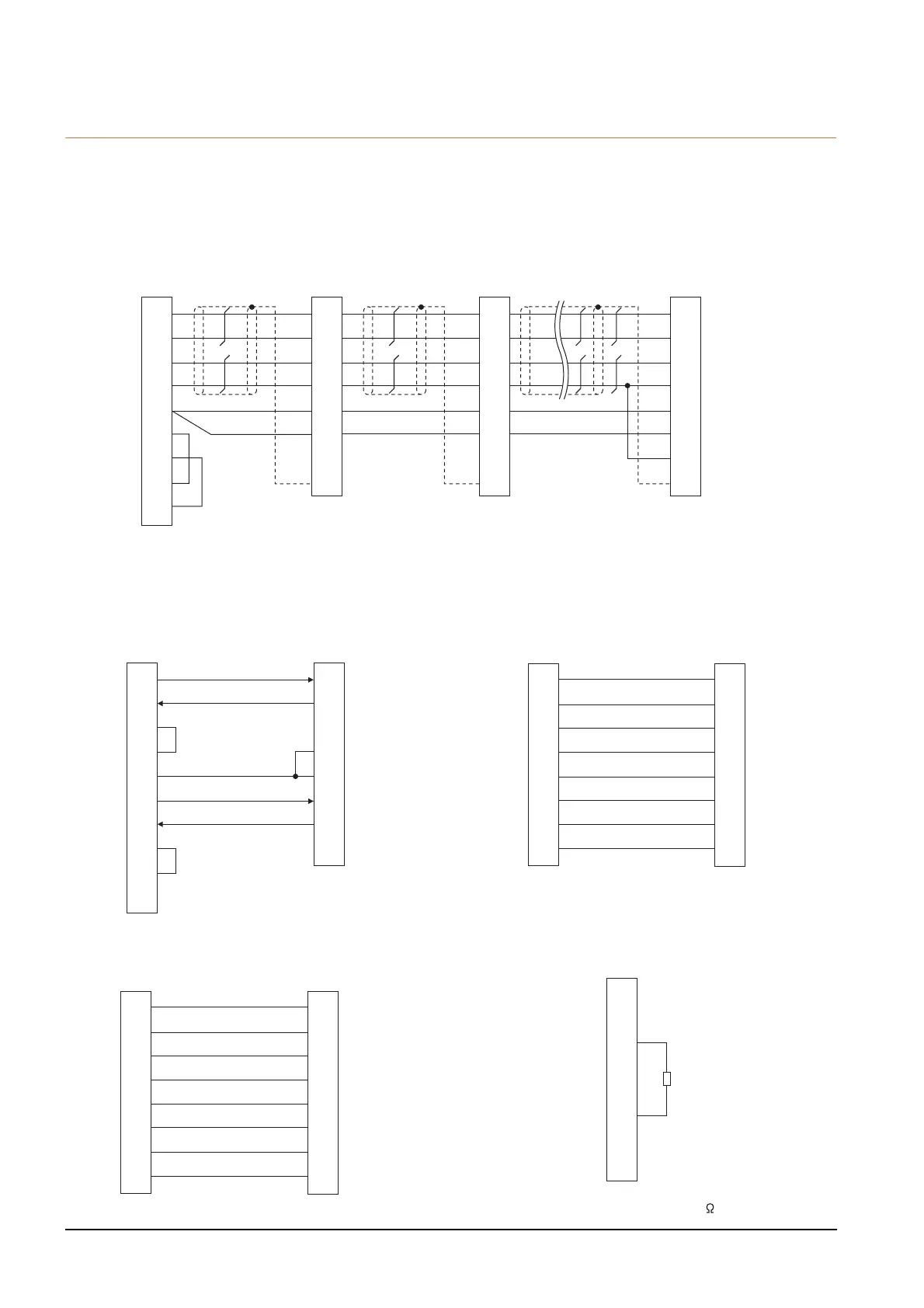
Connection diagram
*1 At the last axis, connect TRE to RDN.
(1) RS422 connection diagram 1)
GOT side
SDP
SDN
RDP
RDN
LG
LG
TRE
SD
Connector for
interface unit's
or
2nd axis servo
amplifier's CN3
SDP
SDN
RDP
RDN
LG
LG
TRE
SD
RXD+(RDA)
RXD-(RDB)
TXD+(SDA)
TXD-(SDB)
SG(GND)
RTS+(RSA)
RTS-(RSB)
CTS+(CSA)
CTS-(CSB)
2
7
1
6
5
3
8
4
9
9
19
5
15
11
1
10
Plate
9
19
5
15
11
1
10
Plate
Connector for
interface unit's
or
1st axis servo
amplifier's CN3
Connector for
interface unit's
or
32nd axis (last axis)
servo amplifier's CN3
*1
SDP
SDN
RDP
RDN
LG
LG
TRE
SD
9
19
5
15
11
1
10
Plate
(2) RS422 connection diagram 2)
(3) RS422 connection diagram 3)
1
2
3
4
5
6
7
8
9
-
GOT side
Distributor side
(Modular connector)
3
5
2
7
1
6
4
8
SDA
RDA
RSA
CSA
SG
SDB
RDB
RSB
CSB
FG
RDP
SDP
P5D
LG
LG
RDN
SDN
NC
1
2
3
4
5
6
7
8
Distributor side
(Modular connector)
Distributor side
(Modular connector)
1
2
3
4
5
6
7
8
LG
P5D
RDP
SDN
SDP
RDN
LG
NC
LG
P5D
RDP
SDN
SDP
RDN
LG
NC
(4) RS422 connection diagram 4)
*1Make the wiring between the distributor and servo amplifier as short as
possible.
(5) RS422 connection diagram 5)
*1 Perform terminal processing on the part between RDP (3-
pin) and RDN (6-pin) with a 150 resistor.
*
1
1
2
3
4
5
6
7
8
Distributor side
(Modular connector)
Servo amplifier side
(Modular connector)
1
2
3
4
5
6
7
8
LG
P5D
RDP
SDN
SDP
RDN
LG
NC
LG
P5D
RDP
SDN
SDP
RDN
LG
NC
1
2
3
4
5
6
7
8
Distributor side
(Modular connector)
LG
P5D
RDP
SDN
SDP
RDN
LG
NC
*
1

 Loading...