15. SERVO AMPLIFIER CONNECTION
15.3 Connection Diagram
15 - 11
SERVO AMPLIFIER CONNECTION
15
Precautions when preparing cable
(1) Cable length
The length of the RS-422 cable must be 30m or less.
(2) GOT side connector
For the GOT side connector, refer to the following.
1.4.1 GOT connector specifications
(3) Servo amplifier connector
Use the connector compatible with the servo amplifier.
For details, refer to the following.
See the technical data of the servo amplifier to
be used.
(a) Servo amplifier connector specifications
• Pin layout in the Modular connector
• Connector of cable between MELSERVO Series
servo amplifiers
• Use the commercial connectors and cables
shown in the table below or the comparable
products.
(Refer to the manual for the servo amplifier.)
Connecting terminating resistors
(1) GOT side
Set the terminating resistor setting switch to "Disable".
For the procedure to set the terminating resistor, refer
to the following.
1.4.3 Terminating resistors of GOT
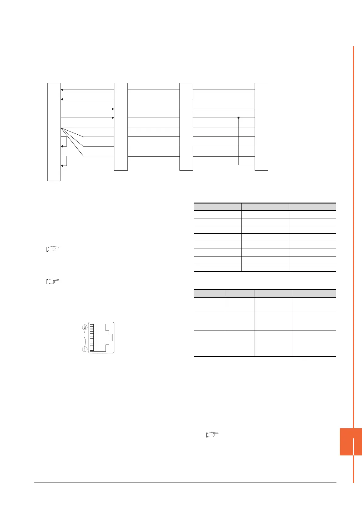
(6) RS422 connection diagram 6)
*1 At the last axis, connect TRE to RDN
13
14
39
40
3
28
30
34
31
SDP
SDN
RDP
RDN
LG
LG
LG
LG
TRE
SDP
SDN
RDP
RDN
LG
LG
LG
LG
TRE
RDA
RDB
SDA
SDB
SG
RSA
CSA
RSB
CSB
FG
2
7
1
6
5
3
4
8
9
ー
13
14
39
40
3
28
30
34
31
1st axis servo
amplifier's CN1
SDP
SDN
RDP
RDN
LG
LG
LG
LG
TRE
13
14
39
40
3
28
30
34
31
GOT side
2nd axis servo
amplifier's CN1
32nd axis (last axis)
servo amplifier's CN1
*1
When seen from the front of the servo amplifier
(receptacle side)
Modular jack
Pin No. Signal name Remark
1LG
2P5D
3 RDP
4SDN
5SDP
6 RDN
7LG
8NC
Name Model name Specifications Manufacturer
Connector
TM10P-88P
(Plug)
RJ45 connector
HIROSE ELECTRIC
CO.,LTD.
Modular
ceiling rosette
(Distributor)
BMJ-8 -
HAKKO ELECTRIC
CO.,LTD.
TEL(03)-3806-9171
Cable -
Cable conforming
to EIA568
(such as cable
10BASE-T)
-

 Loading...


