10 - 8
10. CC-Link IE CONTROLLER NETWORK CONNECTION
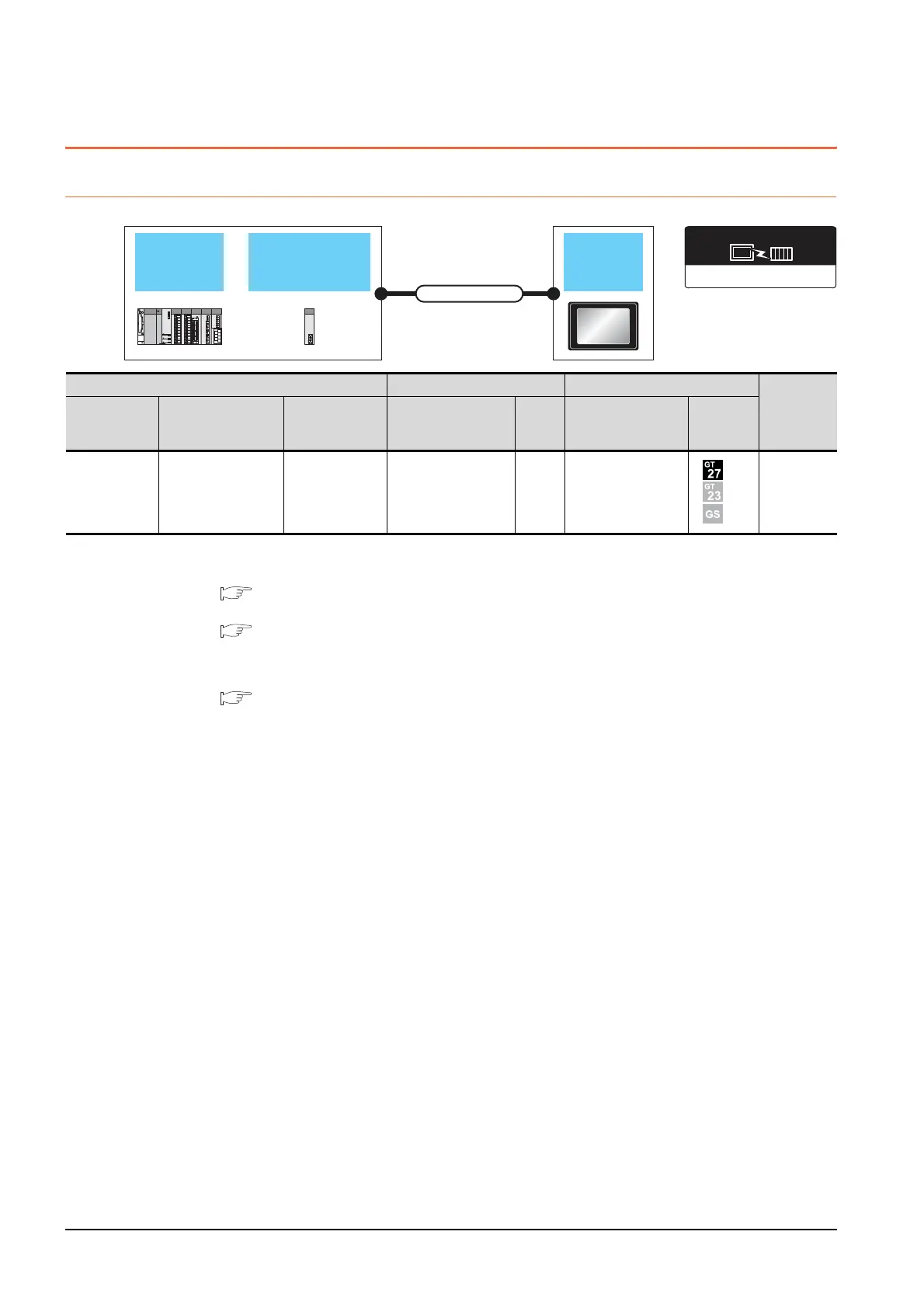
10.2 System Configuration
10.2 System Configuration
10.2.1 Connecting to optical loop system
*1 When the CC-Link IE Controller Network is in the extended mode, use a unit with the upper five digits of the serial No. 12052 or
later.
For the system configuration on the CC-Link IE Controller Network module side, refer to the following manual.
CC-Link IE Controller Network Reference Manual
*2 For the optical fiber cable, refer to the following manual.
CC-Link IE Controller Network Reference Manual
*3 The overall extension cable length and the length between stations vary depending on the cable type to be used and the total
number of stations.
For details, refer to the following manual.
CC-Link IE Controller Network Reference Manual
*4 When Universal model QCPUs is a control station, up to 119 GOTs can be connected.
When a QCPU other than Universal model QCPU is the control station, the number of connectable GOTs is 63 units (at most).
Basic model QCPU and the QSCPU cannot be used as the control station.
*5 When the CC-Link IE Controller Network is in the extended mode, only MELSEC-Q series Universal model QCPU can be used.
*6 When the CC-Link IE Controller Network is in the extended mode, use a module with the serial No. 02910908******* or later.
CC-Link IE controller
network module
QCPU
GOT
Connection cable
CC-Link IE Controller Network
Communication driver
PLC Connection cable GOT
Number of
connectable
equipment
Model name
*5
CC-Link IE controller
network
communication unit*1
Communication
type
Cable model
Max.
distance
Option device Model
MELSEC-Q
C Controller
module
MELSEC-QS
QJ71GP21-SX
QJ71GP21S-SX
CC-Link IE
Optical fiber cable
*2
*3
GT15-J71GP23-SX
*6
119 GOTs
*4

 Loading...


