4. HOW TO MONITOR REDUNTANT SYSTEM
4.2 Direct CPU Connection
4 - 11
4
HOW TO MONITOR REDUNTANT SYSTEM
4.2 Direct CPU Connection
This section describes the direct CPU connection by which a GOT is connected to a PLC CPU in the redundant system.
Two methods for the CPU direct connection, using one or two GOTs, are available.
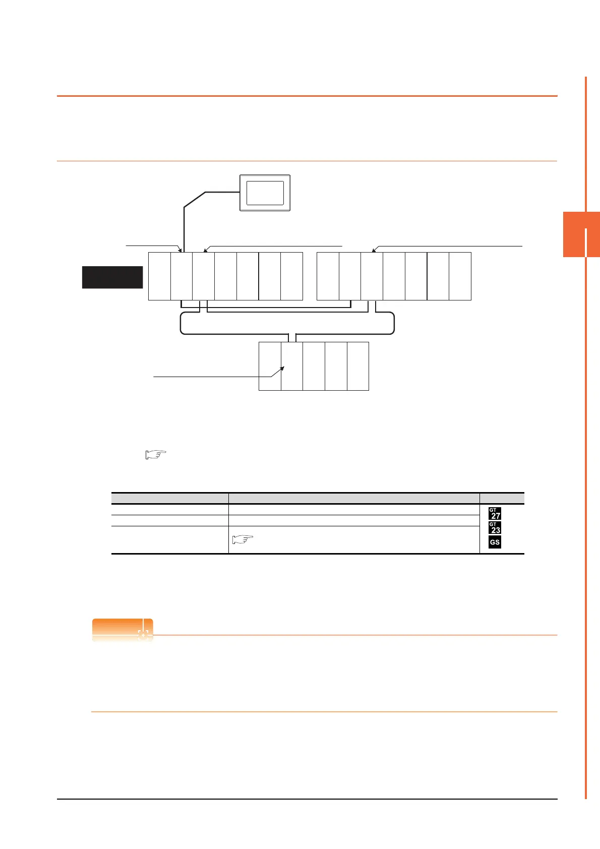
4.2.1 When using one GOT
(1) Connection method
Connect the GOT to the RS-232 interface of the control system CPU module (Q12PRHCPU, Q25PRHCPU) of
the redundant system.
For details, refer to the following.
6. DIRECT CONNECTION TO CPU
(2) GT Designer3 setting
Set GT Designer3 as follows.
(3) Monitoring target change when system switching occurs in a redundant system
When the system switching occurs, the PLC CPU (other station) of the control system after system switching
takes over the host station operation.
Since the GOT monitors the control system, the monitoring target is automatically changed to other station.
To monitor the control system without Q redundant setting
If the system switching occurs when the Q redundant setting is not made, the GOT cannot change the monitoring
target at the occurrence of system switching since it monitors the connected PLC CPU (host station).
As a countermeasure, change the cable connection from the PLC CPU in the previous control system to the control
system after system switching.
Setting item Settings Model
Controller Type MELSEC-Q/QS, Q17nD/M/NC/DR, CRnD-700
Device setting (Network setting) Host
Q Redundant Setting
4.9 Q Redundant Setting
Monitor target
MELSECNET/H remote I/O network
CPU direct connection
GOT
Network No. 1, Station No. 0
(Multiplexed remote master station)
Control system
(System A)
Q25PRHCPU
Power
supply module
QJ71LP21-25
QJ71BR11
QJ71E71-100
QJ61BT11N
Empty
Power
supply module
Empty
Power
supply module
Empty
Empty
Network No. 1, Station No. 1
(Multiplexed remote sub master station)
Standby system
(System B)
QJ72LP25-25
QJ71C24N
Network No. 1, Station No. 2
(remote I/O station)
Q25PRHCPU
QJ71LP21-25
QJ71BR11
QJ71E71-100
QJ61BT11N

 Loading...


