5 - 22
5. ETHERNET CONNECTION
5.4 PLC Side Setting
(3) Ethernet setting
*1 Set the same value as that of GOT N/W No.
*2 Set a value different from that of the GOT PLC No. and the
PLC No. of other PLCs on the same network.
Checking communication state of Connecting
to Built-in Ethernet port CPU
(1) When using the Command Prompt of Windows
.
Execute a Ping command at the Command Prompt of
Windows
.
(a) When normal communication
C:\>Ping 192.168.3.1
Reply from 192.168.0.1: bytes=32 time
<10ms TTL=32
(b) When abnormal communication
C:\>Ping 192.168.3.1
Request timed out.
(2) When abnormal communication
At abnormal communication, check the followings and
execute the Ping command again.
• Cable connecting condition
• Confirmation of switch and network parameter setting
• Operation state of PLC CPU (faulty or not)
• The IP address of Built-in Ethernet port CPU specified
in the ping command
Ethernet diagnostics of GX Developer
Ethernet diagnostics of GX Developer is available to a
Ping test from the PLC.
For details of Ethernet diagnostics of GX Developer,
refer to the following manual.
QCPU User's Manual (Hardware Design,
Maintenance and Inspection)
MELSEC-L CPU Module User's Manual
(Hardware Design, Maintenance and
Inspection)
5.4.3 Connecting to Ethernet
module (Q/L Series)
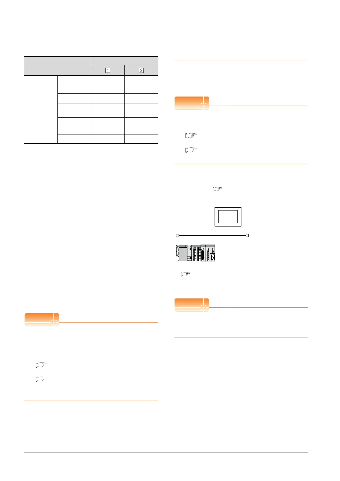
This section describes the settings of the GOT and
Ethernet module (Q Series) in the following case of the
system configuration.
Ethernet module (Q/L Series)
For details of the Ethernet module (Q/L Series), refer
to the following manual.
Q Corresponding Ethernet Interface Module
User's Manual (Basic)
MELSEC-L Ethernet Interface Module User's
Manual (Basic)
System configuration (for Q series)
*1 The Ethernet module is mounted on the base unit slot 0.
The Start I/O No. of the Ethernet module is set to "0".
When connecting to Q170MCPU
When connected to Q170MCPU, the start I/O No. of
the Ethernet module is set to "70".
Item
Set value
Ethernet setting
No.1
Host * -
N/W No.
1
*1
1
*1
PLC No.
2
*2
3
*2
Type
QnUDE(H),
LCPU
QnUDE(H),
LCPU
IP address 192.168.0.1 192.168.0.2
Port No. 5006 (fixed) 5006 (fixed)
Communication UDP (fixed) UDP (fixed)
<GOT> (The settings other than the
following are set to the default)
*1
Network No. : 1
PLC No.
: 1
IP address
: 192.168.3.18
Port No.
: 5001
Communication format
: UDP (fixed)
Network No. : 1
PLC No. : 2
IP address : 192.168.3.19
Port No. : 5001
Communication format : UDP(fixed)
<Ethernet module> (The settings other than the
following are set to the default)
[Controller Setting] and [Ethernet] of GT
Designer3
■
■ [Network parameter] of GX Developer

 Loading...


