7. COMPUTER LINK CONNECTION
7.3 Connection Diagram
7 - 15
7
COMPUTER LINK CONNECTION
7.3 Connection Diagram
The following diagram shows the connection between the
GOT and the PLC.
7.3.1 RS-232 cable
Connection diagram
Precautions when preparing a cable
(1) Cable length
The length of the RS-232 cable must be 15m or less.
(2) GOT side connector
For the GOT side connector, refer to the following.
1.4.1 GOT connector specifications
7.3.2 RS-422 cable
Connection diagram
Precautions when preparing a cable
(1) Cable length
The length of the RS-422 cable must be 1200m or less.
(2) GOT side connector
For the GOT side connector, refer to the following.
1.4.1 GOT connector specifications
Connecting terminating resistors
(1) GOT side
Set the terminating resistor setting switch to "Disable".
For the procedure to set the terminating resistor, refer
to the following.
1.4.3 Terminating resistors of GOT
(2) Serial communication module or computer link
module side
Connect the terminating resistors (330 1/4W (orange/
orange/brown/ ) ) on the serial communication module
or computer link module side. For details, refer to the
following manual.
User's Manual for the serial communication
module or computer link module
(a) Other than A2CCPUC24(-PRF)
Connect the terminating resistors supplied with the
module across RDA and RDB.
(b) A2CCPUC24(-PRF)
Set TXD and RXD on the terminating resistor
setting pin to "A".
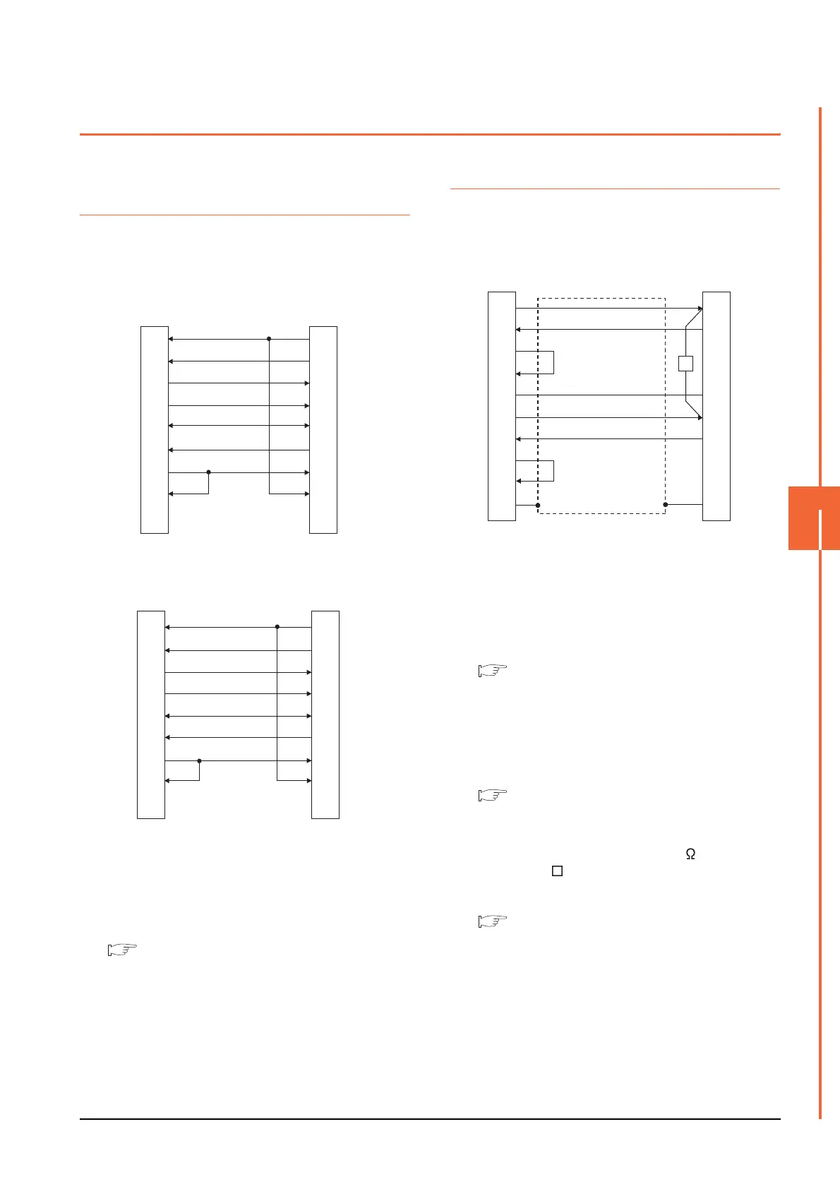
(1) RS232 connection diagram 1)
PLC side connector D-sub 9-pin
(2) RS232 connection diagram 2)
PLC side connector D-sub 25-pin
GOT side
(D-Sub 9-pin)
1
2
3
4
5
6
7
8
9
PLC side
7
3
2
6
5
4
1
8
9
CD
RD(RXD)
SD(TXD)
ER(DTR)
SG
DR(DSR)
RS(RTS)
CS(CTS)
-
RS(RTS)
SD(TXD)
RD(RXD)
DR(DSR)
SG
ER(DTR)
CD
CS(CTS)
-
GOT side
(D-Sub 9-pin)
PLC side
1
2
3
4
5
6
7
8
9
4
2
3
6
7
20
8
5
1
CD
RD(RXD)
SD(TXD)
ER(DTR)
SG
DR(DSR)
RS(RTS)
CS(CTS)
-
RS(RTS)
SD(TXD)
RD(RXD)
DR(DSR)
SG
ER(DTR)
CD
CS(CTS)
FG
(1) RS422 connection diagram 1)
GOT side
PLC side
1
2
3
4
5
6
7
8
9
-
SDA
RDA
RSA
CSA
SG
SDB
RDB
RSB
CSB
FG
RDA
SDA
-
-
SG
RDB
SDB
-
-
FG
R

 Loading...


