6. DIRECT CONNECTION TO CPU
6.3 Connection Diagram
6 - 21
6
DIRECT CONNECTION TO CPU
6.3 Connection Diagram
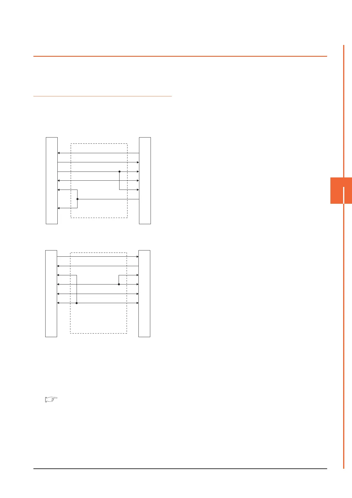
The following diagram shows the connection between the
GOT and the PLC.
6.3.1 RS-232 cable
Connection diagram
Precautions when preparing a cable
(1) Cable length
The length of the RS-422 cable must be within the
maximum distance specifications.
(2) GOT side connector
For the GOT side connector, refer to the following.
1.4.1 GOT connector specifications
(1) RS232 connection diagram 1)
RS232 connection diagram 2)
GOT side
1
2
3
4
5
6
7
8
9
FX PLC side
(D-sub 9-pin)
1
3
2
6
5
8
4
7
9
GOT side
FX PLC side
(D-sub 25-pin)
2
3
8
4
5
6
2
3
5
6
7
20

 Loading...


