14 - 16
14. INVERTER CONNECTION
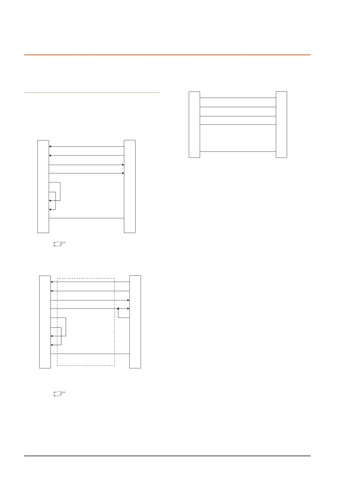
14.3 Connection Diagram
14.3 Connection Diagram
The following diagram shows the connection between the
GOT and the inverter.
14.3.1 RS-485 cable
Connection diagram
(1) RS485 connection diagram 1)
*1 Set the terminating resistor to "Disable".
1.4.3 Terminating resistors of GOT
(2) RS485 connection diagram 2)
*1 Connect a terminating resistor jumper to RDB and
RDR.The terminating resister jumper is packed together
with the FR-A5NR.
*2 Set the terminating resistor to "Disable".
1.4.3 Terminating resistors of GOT
GOT side
*
1
RDA
RDB
SDA
SDB
RSA
RSB
CSA
CSB
SG
FG
5
4
3
6
2
8
-
-
1
2
7
1
6
3
8
4
9
5
-
SDA
SDB
RDA
RDB
P5S
P5S
-
-
SG
Inverter or Distributor side
(Modular connector)
RDA
RDB
SDA
SDB
RSA
RSB
CSA
CSB
SG
FG
2
7
1
6
3
8
4
9
5
-
SDA
SDB
RDA
RDB
RDR
SG
FR-A5NR side
(terminal block)
*
1
GOT side
*
2
(3) RS485 connection diagram 3)
SDA
SDB
RDA
RDB
P5S
P5S
SG
5
4
3
6
2
8
1
5
4
3
6
2
8
1
SDA
SDB
RDA
RDB
P5S
P5S
SG
Inverter side or distributor side
(Modular connector)
Distributor side
(Modular connector)

 Loading...


