4 - 22
4. HOW TO MONITOR REDUNTANT SYSTEM
4.5 MELSECNET/H and MELSECNET/10 Connections (Network Systems)
4.5 MELSECNET/H and MELSECNET/10 Connections
(Network Systems)
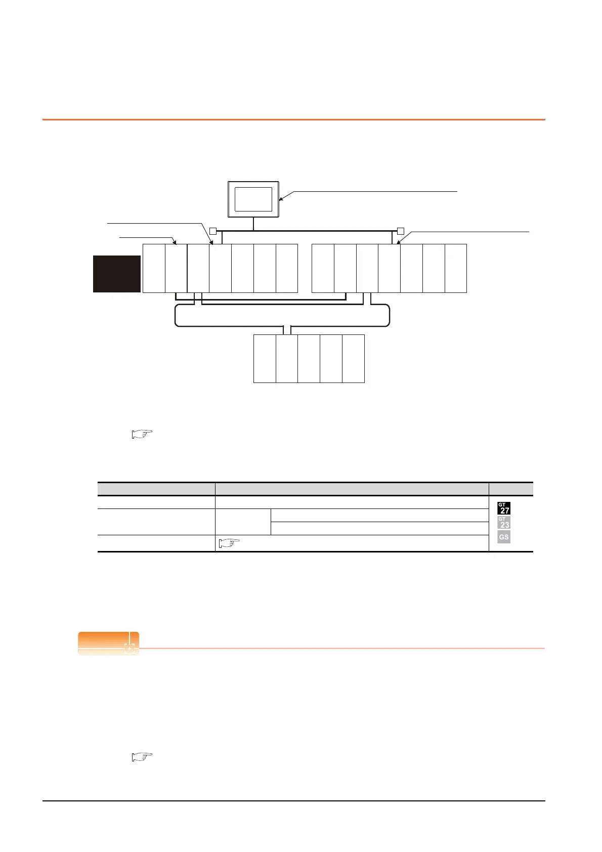
This section explains the MELSECNET/H and MELSECNET/10 connections (network systems) that connect the GOT to
the MELSECNET/H and MELSECNET/10 network system.
The following provides an example of connecting the GOT set as a normal station to the MELSECNET/ H network
system.
(1) Connection method
Connect the MELSECNET/H network system to the GOT.
For details, refer to the following.
9. MELSECNET/H CONNECTION (PLC TO PLC NETWORK), MELSECNET/10 CONNECTION
(PLC TO PLC NETWORK)
(2) GT Designer3 setting
Set GT Designer3 as follows.
(3) Monitoring target change when system switching occurs in a redundant system
When system switching occurs, the network module station No. 2 changes from the normal station to the sub
control station and takes over the control of the MELSECNET/H network system.
Since the GOT monitors the control system, the monitoring target is automatically changed to the network
module station No. 2.
To monitor the control system without Q redundant setting
When system switching occurs, the network module station No. 2 changes from the normal station to the sub
control station and takes over the control of the MELSECNET/H network system.
Since the GOT monitors the station of the specified station number, the monitoring target cannot be changed to the
station No. 2 in response to the system switching.
As a countermeasure, create a screen to monitor the PLC CPU of the control system by switching the station
numbers between System A and System B using the script function.
4.10 Switch the Monitor Target to the Control System Using the Script Function
Setting item Settings Model
Controller Type MELSEC-QnA, MELDAS C6*
Device setting (Network setting) Other
NW No.: Network No. of MELSECNET/H PLC to PLC network
Station No.: Station number of the control system
Q Redundant Setting
4.9 Q Redundant Setting
Monitor target
MELSECNET/H remote I/O network
Power supply
module
Empty
Empty
GOT
Network No. 1, Station No. 1
(Control station)
Control
system
(System A)
Empty
Q25PRHCPU
QJ71LP21-25
QJ71BR11
QJ71E71-100
QJ61BT11N
Empty
Standby
system
(System B)
Q25PRHCPU
QJ71LP21-25
QJ71BR11
QJ71E71-100
QJ61BT11N
QJ72LP25-25
QJ71C24N
Network No. 1, Station No. 3 (Normal station)
Network No. 1, Station No. 2
(Normal station)
MELSECNET/H PLC to PLC network
(MELSECNET/H mode or
MELSECNET/10 mode)
Power supply
module
Power supply
module

 Loading...


