13. CC-Link CONNECTION (Via G4)
13.3 Connection Diagram
13 - 9
CC-Link CONNECTION (Via G4)
13
13.3 Connection Diagram
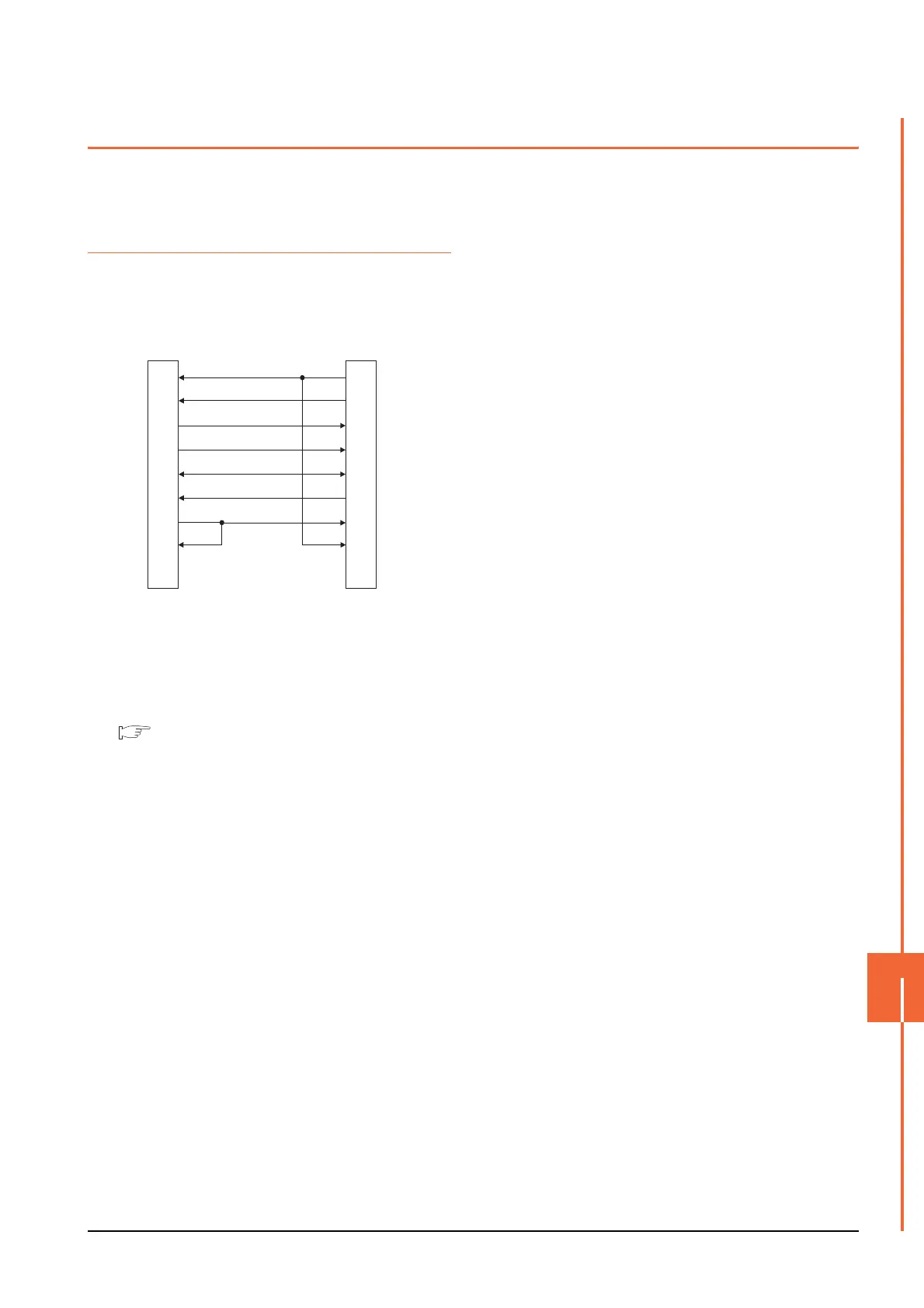
The following diagram shows the connection between the
GOT and the PLC.
13.3.1 RS-232 cable
Connection diagram
Precautions when preparing a cable
(2) Cable length
The length of the RS-232 cable must be 15m or less.
(3) GOT side connector
For the GOT side connector, refer to the following.
1.4.1 GOT connector specifications
(1) RS232 connection diagram 1)
GOT side
(D-Sub 9-pin)
1
2
3
4
5
6
7
8
9
PLC side
7
3
2
6
5
4
1
8
9
CD
RD(RXD)
SD(TXD)
ER(DTR)
SG
DR(DSR)
RS(RTS)
CS(CTS)
-
RS(RTS)
SD(TXD)
RD(RXD)
DR(DSR)
SG
ER(DTR)
CD
CS(CTS)
-

 Loading...


