14 - 36
14. INVERTER CONNECTION
14.5 FREQROL Series Inverter Side Settings
14.5.11 Connecting FREQROL-A800, F800 series
Communication settings
Configure the inverter communication settings by one of the following three methods.
To automatically reconfigure the GOT side communication settings to the inverter side communication settings in
batches and to perform the automatic connection, refer to the following.
(2) Communication settings of inverter (Automatic connection)
To automatically reconfigure the GOT side default communication settings to the inverter side communication
settings in batches, refer to the following.
(3) Automatic setting with Pr.999
To manually reconfigure the GOT side communication settings to the inverter communication settings, refer to the
following.
(4) Communication settings of inverter (Manual setting)
Be sure to perform the inverter reset after updating each parameter.
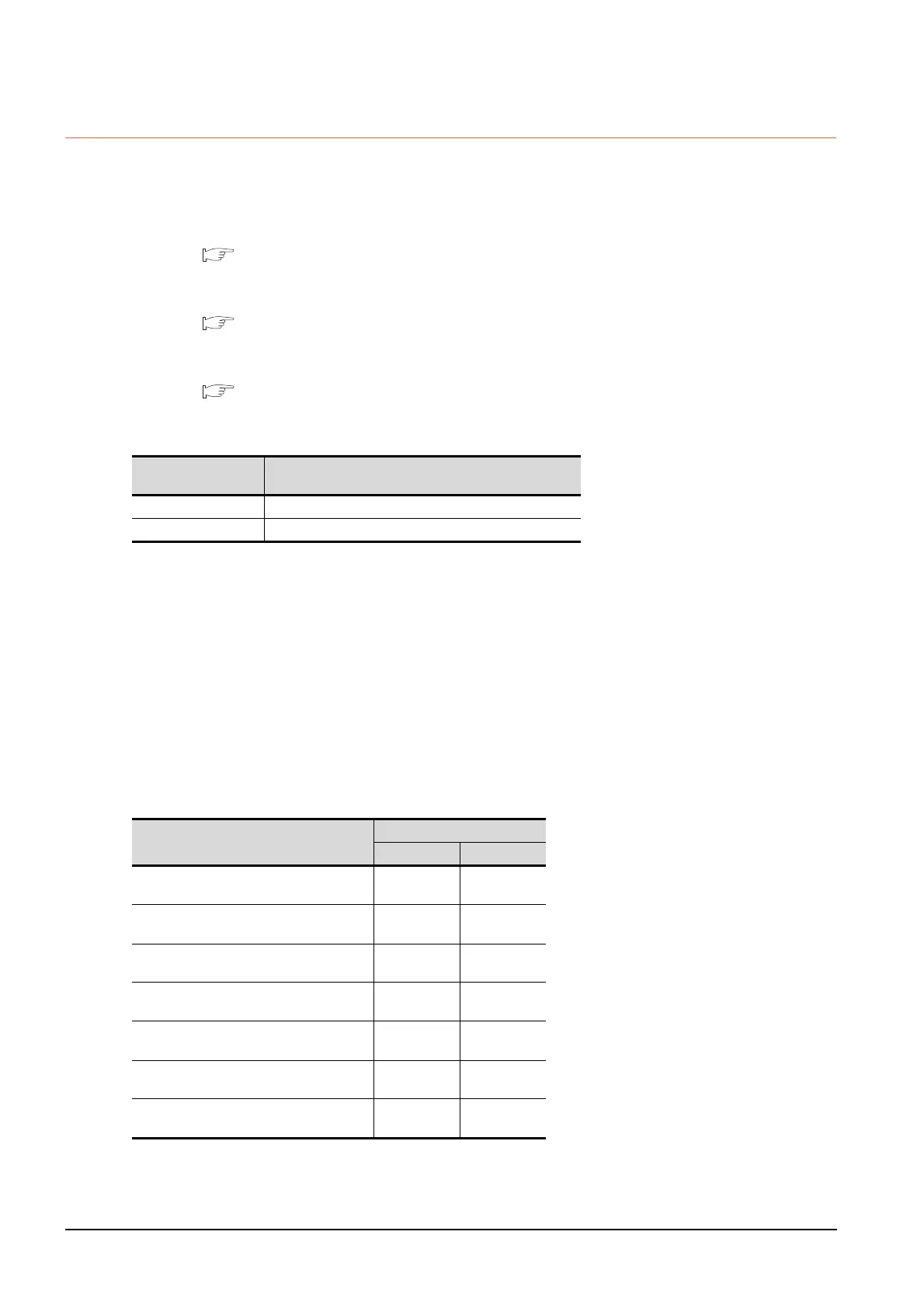
(1) Communication port and corresponding parameters
(2) Communication settings of inverter (Automatic connection)
When [Automatic Negotiation] is set to [Yes] in the GOT communication settings, the inverter parameters are
reconfigured to the GOT communication settings.
Set the station number settings (Pr.117 and Pr.331) and the protocol selection (Pr.549) in advance.
To use the PLC function, set the PLC function operation selection (Pr.414) in advance.
Before performing the automatic connection, connect all the GOTs and the inverters.
After the automatic connection is performed, if a station is added or changed, or the communication settings are
not reconfigured normally, change the settings with the automatic batch parameter setting (Pr.999) separately.
If the inverter power turns off while the automatic connection is executed, execute the automatic connection on
the GOT again.
If the automatic connection fails, a communication timeout error occurs.
If the automatic connection succeeds, the GOT normally starts communicating with each station.
The following shows the parameters to be reconfigured by the automatic connection.
GOT connection
destination
Parameters corresponding to inverter
PU connector Pr.79, Pr.117 to Pr.124, Pr.340, Pr.342, Pr.414
RS-485 terminal Pr.79, Pr.331 to Pr.337, Pr.340 to Pr.342, Pr.414, Pr.549
Setting item
*1
Parameter No.
PU connector RS-485
PU communication speed/
RS-485 communication speed
Pr.118 Pr.332
PU communication stop bit length/
RS-485 communication stop bit length
Pr.119 Pr.333
PU communication parity check/
RS-485 communication parity check
Pr.120 Pr.334
Number of PU communication retries/
RS-485 communication retry count
Pr.121 Pr.335
PU communication check time interval/
RS-485 communication check time interval
Pr.122 Pr.336
PU communication waiting time setting/
RS-485 communication waiting time setting
Pr.123 Pr.337
PU communication CR/LF selection/
RS-485 communication CR/LF selection
Pr.124 Pr.341

 Loading...


