19 - 22
19. MULTI-CHANNEL FUNCTION
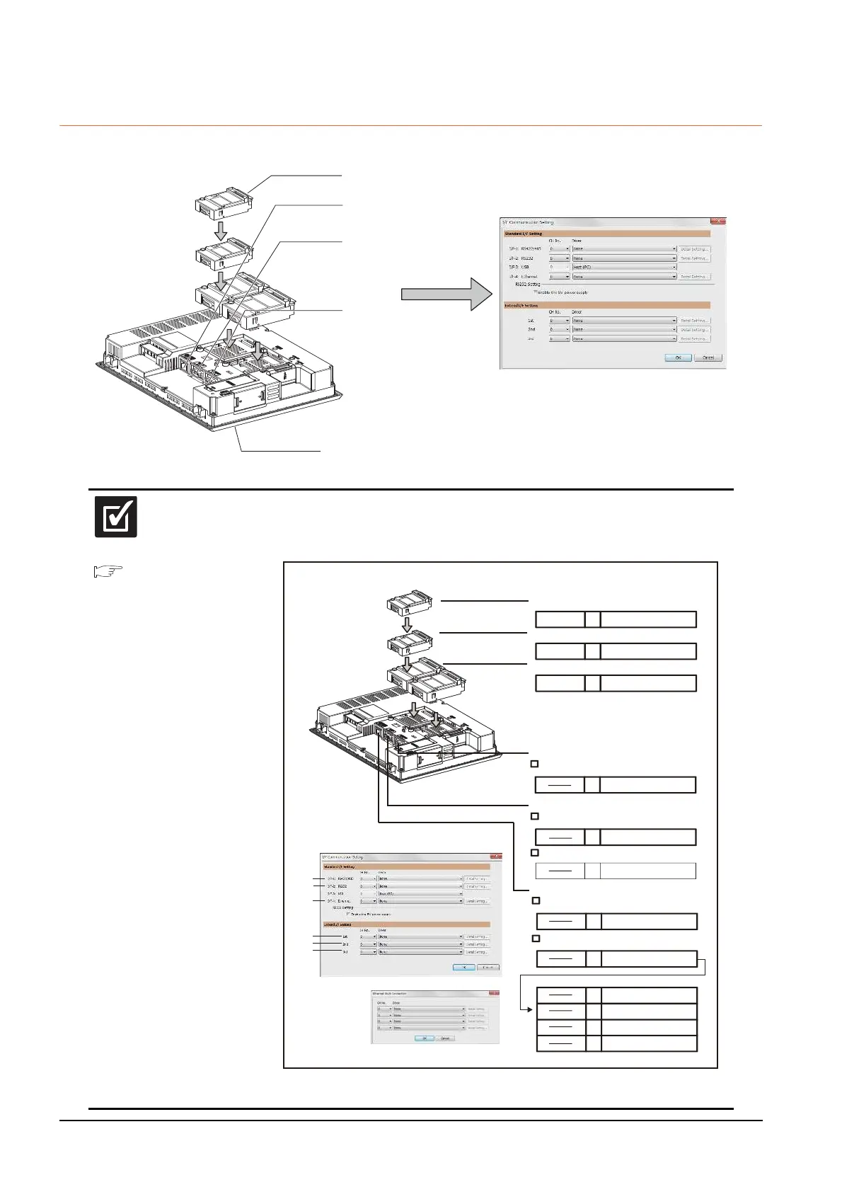
19.3 GOT Side Settings
19.3.5 Setting for communication settings
Make communication settings based on the interface and the installation position of the respective communication units.
3rd stage
2nd stage
1st stage
Extend interface
Standard interface 2
(USB interface built in the GOT)
Standard interface 4
(Ethernet interface
built in the GOT)
Standard interface 1
(RS-232 interface
built in the GOT)
Standard interface 3
(RS-422/485 interface
built in the GOT)
(Example: For GT27)
19.5
Multi-channel Function Check Sheet
Make settings for Communication Settings by GT Designer3 referring to the check sheet
where the necessary information has been written.
The positions that the settings should be made on the communication settings screen are
specified on the check sheet by numbers.
This completes the setting for Communication Settings.
Create a screen with GT Designer3.
(2)
Extension interface
1st stage
2nd stage
3rd stage
Com. unit name CH No.
Driver name
Com. unit name CH No.
Com. unit name
Com. unit name
CH No.
CH No.
Standard interface 2
Connection a controller
Driver name
Connecting a barcode reader, RFID controller,
or personal computer
Driver name
Driver name
(only one connection)
(1)
(3)
(8)
Standard interface 4
Connection a controller (Without multi-channel Ethernet connection)
Driver name
Connection a controller (With multi-channel Ethernet connection)
(only one connection)
(9)
Standard interface 1
Connection a controller
Driver name
(only one connection)
(7)
Driver name
Multi-channel Ethernet connection
Multi
Driver name
Com. unit name CH No.
Com. unit name CH No.
Com. unit name CH No.
Com. unit name CH No.
(1)
(2)
(3)
(9)
(8)
(7)
3rd stage
2nd stage
1st stage
(Example: For GT27)
GT15-RS2-9P
GT15-RS2-9P
GT15-QBUS2
5
4
1
Barcode
MELSERVO-J4,J3,J2S/M
Bus(Q)
OMRON THERMAC/INPANEL NEO
RFID
Ethernet (OMRON), Gateway
2
3
8

 Loading...


