4 - 18
4. HOW TO MONITOR REDUNTANT SYSTEM
4.3 CC-Link Connection (Intelligent Device Station)
4.3 CC-Link Connection (Intelligent Device Station)
This section describes the CC-Link connection (intelligent device station) that connects the GOT set as the intelligent
device station to the CC-Link network.
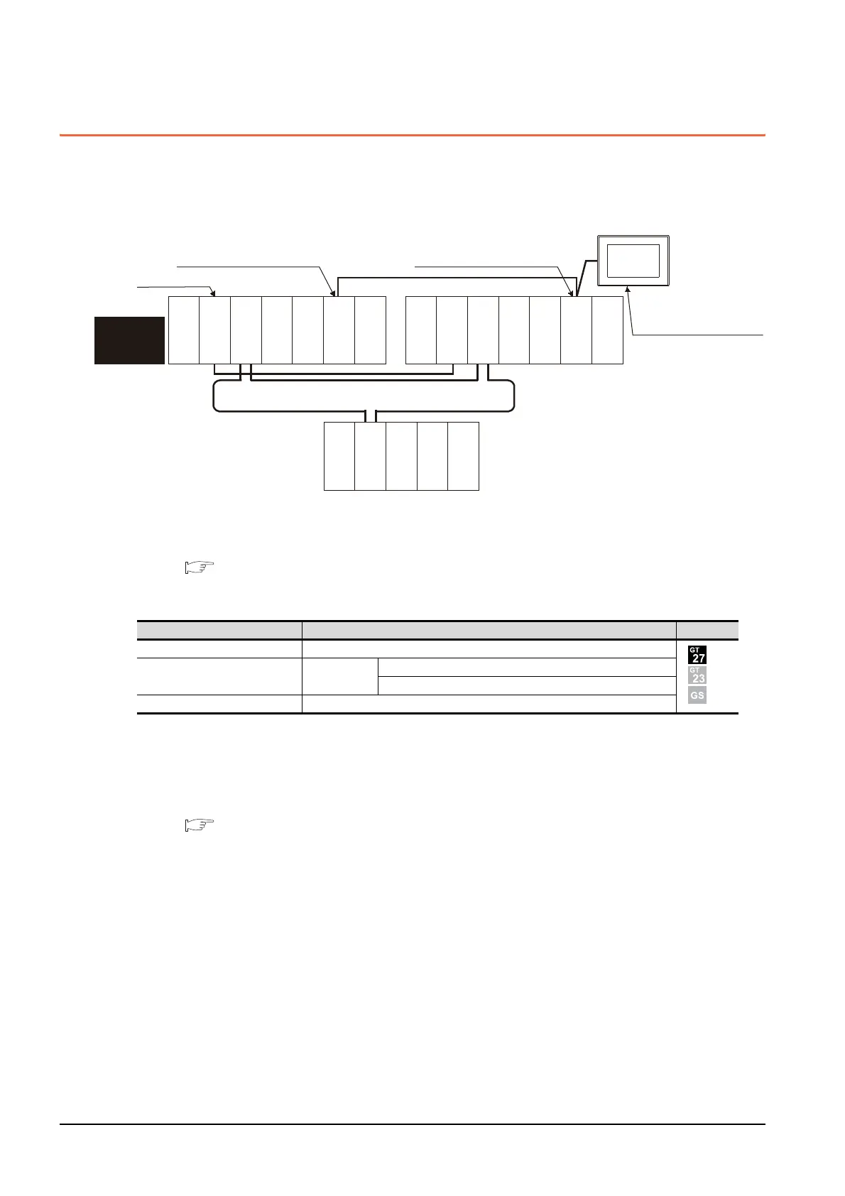
The following shows an example of connecting the GOT set as the intelligent device station to the CC-Link network.
(1) Connection method
Connect the CC-Link network system to the GOT.
For details, refer to the following.
12. CC-Link CONNECTION (INTELLIGENT DEVICE STATION)
(2) GT Designer3 setting
Set GT Designer3 as follows.
In this case, the GOT monitoring is performed by transient transmission of the CC-Link network system.
Therefore, a longer time-lag occurs for displaying objects compared with directly monitoring the PLC CPU.
For displaying objects with a shorter time-lag, set the device for RX, RY, RWw, RWr of the host station set in the
CC-Link network and execute the cyclic transmission.
For details, refer to the following.
3.3 CC-Link System Access Range for Monitoring
Setting item Settings Model
Controller Type MELSEC-QnA, MELDAS C6*
Device setting (Network setting) Other
NW No.: 0 (fixed)
Station No.: 0 (Master station)
Q Redundant Setting Do not set the item.
Monitor target
MELSECNET/H remote I/O network
CC-Link connection
Power
supply module
GOT
Network No. 0, Station No. 0
(Master station)
Control
system
(System A)
Empty
Q25PRHCPU
QJ71LP21-25
QJ71BR11
QJ71E71-100
QJ61BT11N
Network No. 0,
Station No. 2
(Intelligent device station)
Empty
Standby system
(System B)
Q25PRHCPU
QJ71LP21-25
QJ71BR11
QJ71E71-100
QJ61BT11N
QJ72LP25-25
QJ71C24N
CC-Link
Network No. 0, Station No. 1
(Standby master station)
Power
supply module
Power
supply module
Empty
Empty

 Loading...


