1 - 20
1. PREPARATORY PROCEDURES FOR MONITORING
1.4 Connection Cables for the Respective Connection
1.4 Connection Cables for the Respective Connection
To connect the GOT to a device in the respective connection type, connection cables between the GOT and a device are
necessary.
For cables needed for each connection, refer to each chapter for connection.
1.4.1 GOT connector specifications
The following shows the connector specifications on the GOT side.
Refer to the following table when preparing connection cables by the user.
RS-232 interface
Use the following as the RS-232 interface and the RS-232 communication unit connector on the GOT. For the GOT
side of the connection cable, use a connector and connector cover applicable to the GOT connector.
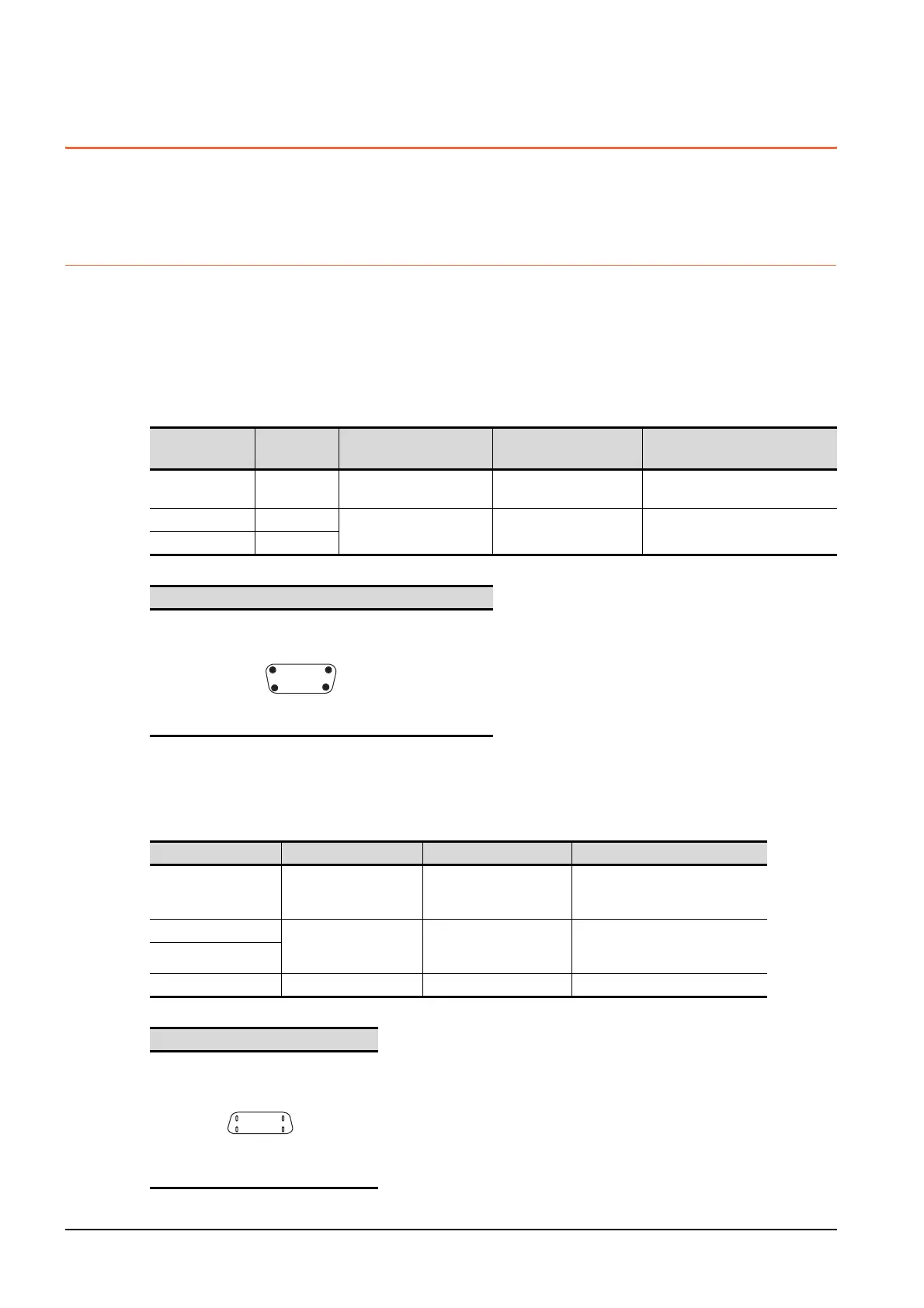
(1) Connector specifications
(2) Connector pin arrangement
RS-422/485 interface
Use the following as the RS-422/485 interface and the RS-422/485 communication unit connector on the GOT.
For the GOT side of the connection cable, use a connector and connector cover applicable to the GOT connector.
(1) Connector model
(2) Connector pin arrangement
GOT
Hardware
Version
*1
Connector type Connector model Manufacturer
GT27
GT23
-
9-pin D-sub (male)
inch screw fixed type
17LE-23090-27(D4C□)DDK Ltd.
GT15-RS2-9P -
9-pin D-sub (male)
inch screw fixed type
17LE-23090-27(D3CC) DDK Ltd.
GT01-RS4-M -
GT27, GT23, GT15-RS2-9P, GT01-RS4-M
GOT Connector type Connector model Manufacturer
GT27
GT23
9-pin D-sub (female)
M2.6 millimeter screw
fixed type
17LE-13090-27(D2AC) DDK Ltd.
GT15-RS4-9S 9-pin D-sub (female)
M2.6 millimeter screw
fixed type
17LE-13090-27(D3AC) DDK Ltd.
GT01-RS4-M
GT15-RS4-TE - - SL-SMT3.5/10/90F BOX
GT27, GT23, GT15-RS4-9P, GT01-RS4-M
9-pin D-sub (male)
GOT main part connector
see from the front
15
69
14-pin (female)
GOT main part connector
see from the front
814
17

 Loading...


